


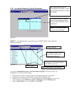
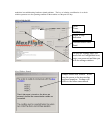
11. When all three green blocks are there, another window will state auto run test completed successfully.
12. Close the window by clicking “OK”
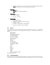
13. Close the program by clicking “X” top right. You are now back to the desktop.
14. System is now ready to perform any other tests or run the program.
CHAPTER 3 MECHANICAL
3-1 Mechanical are those bits and pieces such as nuts, bolts, machined parts and cabinetry
that when assembled correctly make up the major portion of the flight simulator that one
sees. These are the important parts that give the unit substance.
1. “A” frame two each, right and left. See drawing DET-014.
These are assembled from the parts listed in the drawing and make up the supporting
backbone of this machine.
2. Center weldment. See drawing DET-017
Manufactured part by machine welding various machined plates together. The pitch
shafts, tail shaft and counterweight and roll motor and hub assembly are bolted to this
unit.
3. Pitch arms two. See drawing DET-016,017.
Manufactured part. Left side has tail shaft with keyway for the pitch motor mounting and
grooved for the spring retaining clip. It also has mount for the signal pitch rings. Right
side is drilled so that set screws can be inserted into power ring adapter. The shafts are
bolted and safety wired to the center weldment.
4. Tail shaft. See drawing DET-017,018.
Machined part, supports the counterweight, H frame at the rear. Through the center
passes a threaded rod that retains in place the tail shaft retention plug. Bolted and safety
wired to the center weldment.
5. H frame assembly, attached to the tail shaft. See drawing DET-018,017.
Is the mounting support for the tail boom cover, the counterweight drive screw rear
alignment plate and the counterweight side alignment bar.
6. Counterweight gear and gear box.
Sole function is to move the counterweight forwards and rearwards on the tail shaft. This
allows the machine to balance about the pitch shaft axis.
7. Counterweight @300 pounds. See drawing DET-017.
Machined and welded steel plates. Contain slide bushings and a mount for drive clutch at
the top. Its function is to counterbalance the weight of the cockpit area.
8. Chair assembly. See drawing DET-040,041,042.
Machined and welded aluminum square tubing and plates. This is the main support for
the entire cockpit area.
9. Seat back assembly. See drawing DET-040,041,042.
Interface between the roll hub and the seat frame assembly. Transmits roll motion to the
cockpit area. Supports the entire cockpit assembly.
10. Lift drive network. See drawing DET-047,048. See paragraph 3-2 for detailed installation.
This moves the entire motion platform in the vertical axis up or down.
11. Roll motor mounting. See drawing DET-045.
Held to the center weldment by four bolts. Acts as the roll motion generator and the rear
pivot mounting for the roll hub assembly.
12. Pitch motor mounting. See drawing DET-011.
Pitch motor is mounted to the left pitch shaft, by the pitch shaft going through the center
of the pitch gearbox. Prior to mounting, pitch shaft is coated with antiseaze compound.
13. Roll hub assembly. See drawing DET-045.