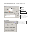
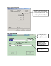
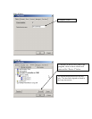
b. Cross lift drive shaft assembly. See DET-047
i. Lay 4 inch C channel flat on floor.
ii. Locate and install Nylon pillow block bearings, spacer plates in pre-
tapped locations inside C channel using ¼ x 20 allen bolts, flat and
lock washers plus loctite.
iii. Feed the ½ inch drive shaft through the center of each bearing.
iv. Install six 5/16 inch allen bolts in locations provided . Used as
leveling posts at install.
v. Locate and place on left side of shaft ½ inch bore coupling, key fitted
to coupling and shaft keyway and one backup lock collar.
vi. Place a ½ inch lock collar onto the left input shaft on gear box.
Allow @ 1/8 inch space between collar and gear box. Torque screws
using loctite.
vii. On right side of drive shaft (gear box end) locate and place a lock
collar, key and star drive half coupling. Fit key to star coupling and
keyway on shaft. Friction fit so you can align items by hand.
viii. Locate and install finger tight gear box to C channel mounts. Install
on C channel using 3/8 inch hex bolts, flat and lock washers.
ix. Place pre-assembled center section between the two A frames
centered on gear boxes both sides.
c. Gear Box Assembly. See DET-048,048A
i. Locate Id plate at rear of gear box and position gear box so label is
up at the top.
ii. Tap the three top holes using a 3/8 inch coarse thread tap @ ½ inch
down.
iii. Locate and install three cut to length threaded rods use loctite at
base.
iv. Locate and place three ¾ inch backup locking collars, place one on
each shaft.
v. Locate and place ¾ inch bore star coupling (2) and key on each end
shaft (end shafts opposing each other), do not torque at this time.
vi. Locate and place a ¾ inch solid coupling, key and place onto the
input shaft of the 90 dgree gear box, do not torque now.
vii. Locate and install a ½ inch star coupling and key onto the right input
shaft of the action jack gear box allowing 1/8 inch space between
coupling and gear box face. Loctite and torque set screw.
viii. Position the nylatron sleeve coupling connector over the right action
jack input coupling.
ix. Position 90 degree gear box right output shaft through large hole
in mount plate. Install finger tight two 5/16 inch coarse bolts and
nuts, and washers through top two mount holes on gear box.
x. Align gear box output coupling with nylatron sleeve allowing 1/8
inch side to side movement of sleeve on couplings.
xi. Tighten set screws on output shaft of gear box coupling and lock
collar.
xii. Position center drive shaft right side to the gear box. Install finger
tight two 5/16 inch bolts, washers through gear box top mount holes
and support brackets of drive shaft assembly.


