


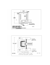
4. Locate the ABS panels for the inside of the A-Frames and their fasteners and
attach to the A-Frames. See reference drawing DET-015. Note if speakers are
mounted to the panels they go to the front.
5. Place A frames in their relative position where the final assembly will take place.
Note, the base C channel that has only one side circle notched in the center is placed
on the right hand side of the machine. DET-016
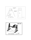
6. Find the center main frame assembly with the cockpit, uncrate and roll into
position between the A-Frames. DET-016
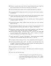
7. Locate the pitch arm assemblies and their bolts. Install pitch arm with keyway on
left side of center weldment with the keyway facing up. The other pitch shaft on the
other side. Loctite with blue, and bolt the pitch arms to the center weldment of the
main frame. Note ensure that the long bolt on each side goes at the 1 O’Clock
position facing the weldment. This insures that the retention plug retaining nut can be
installed correctly. DET-017,018.
8. Torque and safety wire-tie bolts on the pitch arm.DET-018
9. Elevate the main frame and cockpit using the transport dolly. See DET-010,008
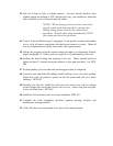
10. Locate the lift jack assemblies, the one with an extension welded to the jack
tower shaft is positioned in the left side, bar extension facing inward on A frame. The
other on the right side. The jackshaft assemblies can be positioned by lifting slightly
on pitch lift blocks, tilt top of jackshaft inward and push gearbox at the base into
position. Tilt top back to center. Fasten to lift blocks and install guide plates at the
base. See DET-043
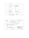
11. Stabilize the A-Frames and slide them onto each pitch shaft. Ensure that the
thrust rings are on the shafts loosely prior to application of the A-Frames. DET-
008
12. Locate power slip ring and thrust ring. Position thrust ring onto right pitch shaft.
Feed the cabling from power rings through the pitch shaft into the center
weldment area. Secure slip ring with set screws. See DET-044
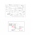
13. Locate and position tail stand at rear of unit. Have one person control platform
motion while lowering transport dolly. When dolly is all the way down adjust
platform position in pitch and remove dolly from area. Place tail stand under tail
boom H frame. Note: If platform is nose heavy place a blanket or other soft
material on floor under the cockpit area and allow cockpit to rest on the floor.
The counterweight needs AC power to reposition and balance. DET-010
14. Position transport dolly on left side of A frame with pitch motor facing A frame in
the center near pitch shaft. Using the current approved lifting method attach and
lift pitch motor from transport dolly up and near the pitch shaft. Install thrust ring