


A machined steel part. Transmits roll motion to the cockpit area ,holds the roll slip rings,
is bolted to the seat back assembly and passes through the roll motor gearbox.
14. Fiberglass cockpit shells. See drawing DET-040.
A manufactured series of fiberglass panels, bolted together to form the upper and lower
cockpit shell assemblies. It is mounted to and completely encloses the seat frame
assembly.
15. Front stand. See drawing DET-005,013.
Assembled steel frame. Supports the front of the lower cockpit. This unit is adjustable
and controls the initial roll encoder alignment during startup of raise command.
16. Rear stand. See drawing DET-010.
Works in conjunction with front stand. Supports the tail boom and cover when motion
platform is in the lowered position.
17. Entry stair assembly. See drawing DET-013.
Manufactured wood product. Enables patrons easy access and egress from the motion
platform cockpit.
18. Cabinetry. See drawing DET-012,009.
Encloses the right and left “A” frame and its contents. Gives a pleasing
visual effect to the machine. Manufactured from wood product.
19. Control Cabinet and Kiosk. See drawing DET-006.
These cabinets are manufactured wood product. Designed to hold all the
controlling electronics for the motion platform.
3-2 Lift Component Installation Procedures
The lift components consist of action jack assembly, jack lift tube to pitch lift block assy., cross drive
shaft, 90 degree gear box, main drive shaft to motor coupling and 3HP lift motor. In order to assure a
smooth operation of the lift system the following installation procedures must be followed. References
will be made to various drawings that are part of the installation manual.
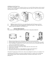
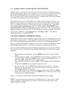
a. Action jack/lift tube assembly. See DET-043,043A,043B
i. Position Action Jack flat on a surface with screw portion upwards.
Make sure that you do not move the Ball Nut assy. past the top
threads or the unit will be damaged by the lift bearings falling out.
See DET-043B for detail.
ii. Raise the ball nut and collar upwards @ 6-8 inches. This will allow
access to the recessed mount holes at the bottom of the collar.
Support one side with a stick or have someone hold the nut assy. so
you can slide the lift tube over screw and onto the collar.
iii. Allign the four mounting holes and install ¼ x20 allen head bolts
with blue loctite and torque into place. Repeat procedure for second
unit assy.
iv. Remove stick and allow lift tube to slowly spin down onto the gear
box. Align tube and gear box by turning the input shaft on the gear
box.
v. Install one side of guide plate onto the lift jack tube.
vi. Place assembly between the two verticals between base and pitch lift
block
vii. Attach lift tube top to the pitch lift blocks using ¼ x 20 lock washers
and loctite.
viii. Align gear box inside torque braces at base and install tie down clips
on all corners.