


CHAPTER 2 – ELECTRICAL SYSTEM
2-1 Electrical System
The electrical system provides the force for the motion of the unit during operation. The motion
base is a two-axis system with a lifting system for raising the unit to the operation position, and a
counterweight system for balancing the cockpit. Each of the axes has an electric motor that
drives in two directions. 208-volt 3-phase powered, variable frequency inverters control these
motors. Sending a DC analog signal from a remote computer to the inverters can set the direction,
position and speed of the motors precisely. The RS-485 connection is a serial communication
path between the inverters and the computer, which allows the computer to monitor and send
commands to the inverters.
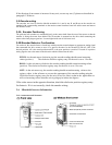
Located inside the right A-Frame, the electrical panel incorporates all the electronics mentioned
above. The panel contains fourteen (14) connectors, namely the main power, pitch motor power,
pitch motor brake power, lift motor power, lift motor brake power, fan power, roll motor power,
roll motor brake power, counterweight motor power, counterweight motor brake power, two RS-
485 communication ports (one spare), inverter speed analog signal, and emergency stop button
connector. Four Mitsubishi inverters are mounted inside the panel. Pitch, roll, and lift run on
bigger units; the counterweight runs on a smaller unit. See panel drawings at the end of this
manual for more information about where they are mounted in the Electrical Control Box.
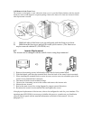
10Base-T networking receptacles are used for the RS-485 communication ports. Hubbell twist
lock connectors are used for the main, pitch motor, roll motor, and lift motor power. All other
connectors are military style connectors.
Motor power connections provide 208-volt 3-phase power to the Pitch, Roll and Lift motors, and
brake power connections provide power to the motor brakes. The counter-weight motor brake is
powered by 110-volt single-phase system the rest are 220. The frequency inverters ensure that the
brakes are not applied during motion.
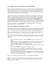
The computer program knows the position of the unit by reading the encoders on the pitch, roll,
and lift axis. The encoders are electrical devices powered by a 5-volt supply on the motion
control interface card, movement can be measured by sending a light beam through a metal disc
that has 400 holes/slits on it. Each light or dark sends a pulse to the Computer Motion Control
Board, which “reads” the pulses and determines where in the pitch, roll and lift axis the motion
platform is at any given time. The encoders know the position of each axis to within .006”. There
is a safety backup to the encoders and that is software driven. It monitors the Roll and Pitch
platform position. If the computer requests movement and does not get an encoder return signal
it will default and shut down motion to the platform. Also should there be a motion on the
platform greater than 15 degrees, that was not requested by the computer the computer will stop
motion of the platform.
The counterweight is used to balance the cockpit and tail section at their vortex, referred to as the
center weldment. The balance is obtained by powering a drive motor, located on top of the
weldment, which moves the counterweight back and forth on a shaft as required to balance the
machine. When the cockpit is balanced, the unit will rise to its maximum up position.