


500 SERIES INSTALLATION MANUAL Page 5-17
P/N 190-00181-02 Rev G
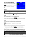
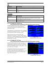
5.3.3 Signal Acquisition Test
Upon approval of the Instrument Panel Self-test Page, the Satellite Status Page is displayed. If the unit is
unable to acquire satellites, relocate the aircraft away from obstructions which might be shading GPS
reception. If the situation does not improve, check the GPS antenna installation.
Once GPS position information is available, use the DIRECT-TO key to activate the navigation function to
a nearby airport, NAVAID, or intersection. Ensure that any connected equipment is transmitting and/or
receiving data from the 500 Series unit and is functioning properly (see the Pilot’s Guide for more
information on the direct-to function).
5.3.4 Deviation & Flags Check
5.3.4.1 Analog Deviation & Flags
The analog deviation (LEFT/RIGHT and UP/DOWN), TO/FROM, and FLAG (lateral and vertical) outputs to a
CDI or HSI should be verified in flight with potential sources of electrical noise such as autopilot, flaps, gear,
heater blowers, etc. operating. Lateral deviation and flags may be checked with either GPS or VOR/ILS, and
vertical deviation and flags must be checked with Glideslope. Verify that the flags are hidden at the correct
times, and that the flag is in view at the correct times.
5.3.4.2 EHSI Deviation Scaling (Only if HSI/CDI is driven by the 500 Series unit via serial data)
With the 500 Series unit locked onto a GPS fix, activate an OBS waypoint about 20 nautical miles from the
present position.
1. With 5.0 nautical mile CDI sensitivity, adjust the OBS course for approximately half-scale deflection
on the 500 Series unit’s Default Navigation page. Verify that the EHSI displays a similar half-scale
deviation.
2. Repeat step 1 with 1.0 nautical mile CDI sensitivity. The CDI sensitivity may be manually set on the
AUX SETUP page, using the “CDI / ALARMS” menu item.
3. Repeat step 1 with 0.3 nautical mile CDI sensitivity.
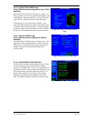
5.3.5 Crossfill Check (Only if dual units installed with RS-232 crossfill connected)
Turn on both 400/500 Series units in the aircraft. For each 400/500 Series unit:
1. Select the first AUX page (titled “FLIGHT PLANNING”).
2. Select “CROSSFILL”.
3. Verify that the displayed status is “Ready”. If “Not Available” is displayed, there may be an RS-232
wiring problem between the two 400/500 Series units.
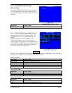
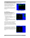
5.3.6 VHF COM Interference Check (GNS 530 Only)
Once the Signal Acquisition Test has been completed successfully, perform the following steps:
1. View the Satellite Status Page and verify that 7 to 8 satellites have been acquired.
2. Verify that the GPS “NAV” flag is out of view.
3. Select 121.150 MHz on the 500 Series COM transceiver.
4. Transmit for a period of 20 seconds.
5. Verify that the GPS “NAV” flag does not come into view.
6. Repeat steps 4 and 5 for the following frequencies:
• 121.175 MHz
• 121.200 MHz
• 131.250 MHz
• 131.275 MHz
• 131.300 MHz
7. Repeat steps 3 through 6 for all COM transceivers installed in the aircraft.
8. If the GPS “NAV” flag comes into view, refer to Section 2.2.7 for options to improve performance.