


Page 5-16 500 SERIES INSTALLATION MANUAL
Rev G P/N 190-00181-02
5.3 ADDITIONAL GROUND TESTS
5.3.1 Connector Engagement Test
1. Turn on the 500 Series unit, and turn on the avionics master switch (if applicable).
2. Place the 500 Series unit in the rack and engage the pawl mechanism.
3. Turn the Allen screw of the locking pawl slowly clockwise until the 500 Series unit just comes on. A
“T” handle makes the turns easy to count, but do not over-tighten.
4. Count the number of complete revolutions you can turn the Allen screw until it can not turn any more
(but take care not to over-tighten). Three turns is the minimum for proper installation. If fewer than
three turns are possible, the mounting rack should be moved aft such that the aircraft panel does not
obstruct the unit from engaging in the rack.
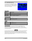
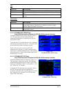
5.3.2 Verification of Self-test Data
Following normal power-up, the Data Base Page is displayed followed by the Instrument Panel Self-Test
Page. Pressing the ENT key once then displays the Instrument Panel Self-Test page (refer to Figure 5-4 on
page 5-5). During this time, many of the electrical outputs are activated so the installation, configuration,
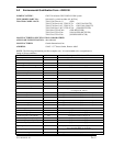
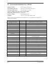
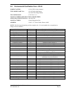
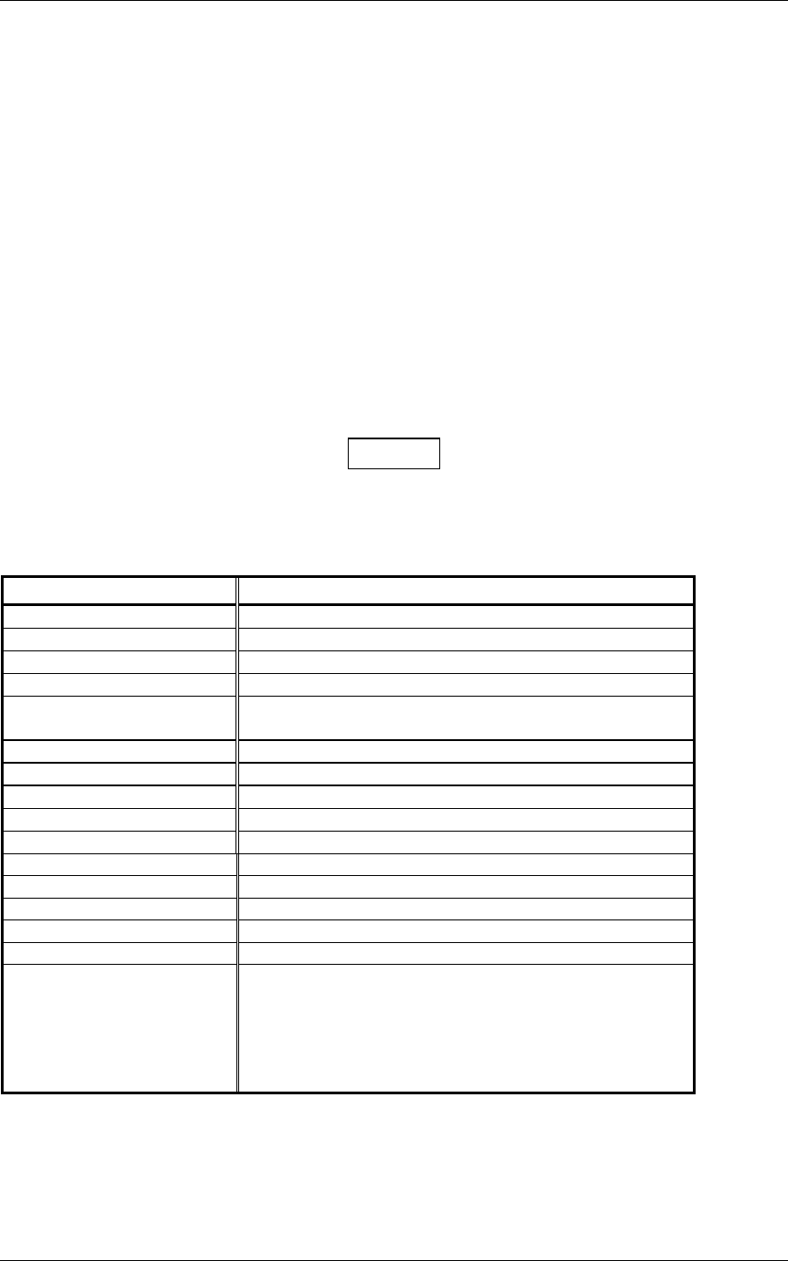
and wiring may be verified. Before approving the Instrument Panel Self-test Page, verify that the
following parameters are displayed on equipment in the aircraft as listed below:
NOTE
Electronic displays which monitor the 500 Series unit’s ARINC 429 output may vary in how and where
annunciations are displayed. Generally, it is not required to verify every data field with an ARINC 429
interface. Correct display of a subset of the data without noting any discrepancies is typically adequate
evidence of correct ARINC 429 operation.
Parameter Self-test Value
Course Deviation
Half-scale left deviation, TO indication, flag pulled
Glideslope/Vert. Deviation
Half-scale up deviation, flag pulled
Bearing to Waypoint
135º
Desired Track
149.5º
Selected Course
500 Series unit displays the OBS value (149.5º if interfaced
to an HSI with driven course pointer).
Distance to Go
10.0 nautical miles
Time to Go
4 minutes
Active Waypoint
“GARMN”
Groundspeed
150 knots
Present Position
N 39º04.05’, W 94º53.86’
Waypoint Alert
Active
Phase of Flight
En Route
Message Alert
Active
Leg/OBS Mode
Leg Mode
GPS Integrity
Reflects actual GPS integrity
Roll Steering (if applicable)
Flight Director commands 0º bank (level flight) for 5
seconds; commands increasing right bank at 1º/second for 5
seconds; commands 5º right bank for 5 seconds; commands
decreasing right bank at 1º/second for 5 seconds, until
command is 0º bank again. This cycle repeats
continuously.