


Page 4-18 500 SERIES INSTALLATION MANUAL
Rev G P/N 190-00181-02
4.9 RMI/OBI
4.9.1 RMI/OBI Function
The MAIN OBI output provides bearing information from the active waypoint for Bendix/King Serial OBI
devices based upon the 500 Series unit’s GPS navigation. For the GNS 530, the MAIN OBI output may be
configured so that it sends VOR/ILS bearing information when VLOC is selected by the GNS 530 CDI
key.
The VOR OBI output provides bearing information from the active waypoint for Bendix/King Serial OBI
devices based upon the GNS 530 VOR receiver.
When a localizer channel is tuned on the VLOC window, there is a bit in the data stream set to indicate that
a localizer frequency is tuned which stows the needle or drive it to the 3 o’clock position.
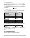
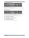
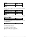
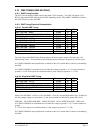
4.9.2 RMI/OBI Electrical Characteristics
Pin Name Connector Pin I/O
MAIN OBI CLOCK P5001 43 Out
MAIN OBI SYNC P5001 45 Out
MAIN OBI DATA P5001 44 Out
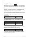
Pin Name Connector Pin I/O
VOR OBI CLOCK P5006 25 Out
VOR OBI SYNC P5006 26 Out
VOR OBI DATA P5006 27 Out
The output driver is active low. The driver output voltage is not more than 1.0 V when sinking 20 mAdc.
The maximum off state leakage current with respect to ground is less than 10 µAdc.
4.9.3 RMI/OBI Configuration
For the GNS 530, refer to section 5.2.8 for the MAIN OBI source configuration.
4.9.4 RMI/OBI Calibration and Checkout
None.
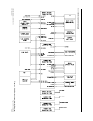
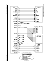
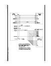
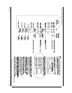
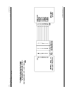
4.9.5 RMI/OBI Interconnect
Refer to Figure 4-21 on page 4-61 for the RMI/OBI interconnect.