


500 SERIES INSTALLATION MANUAL Page 4-13
P/N 190-00181-02 Rev G
The labels recognized on the GPS ARINC 429 IN 1 or GPS ARINC 429 IN 2 ports depend on the
configuration (refer to section 5.2.1).
The 500 Series unit can receive traffic data from a BF Goodrich SKY497 Skywatch system using the GPS
ARINC 429 IN 1 or GPS ARINC 429 IN 2 ports, in order to display traffic information on the 500 Series
unit.
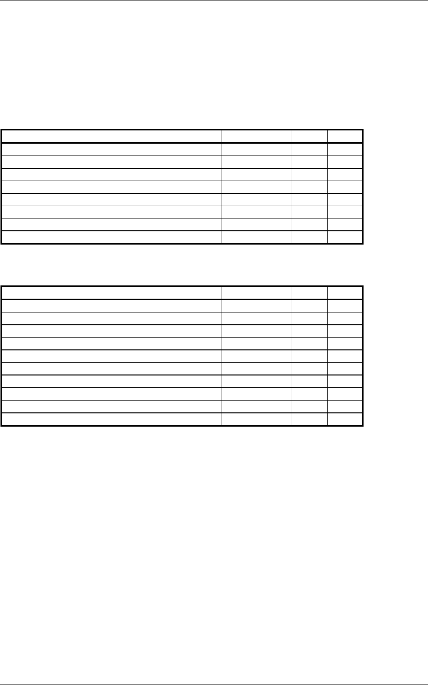
4.6.2 Serial Data Electrical Characteristics
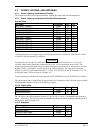
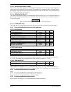
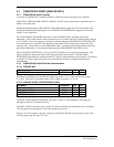
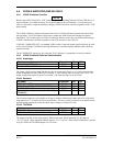
4.6.2.1 RS-232
Pin Name Connector Pin I/O
GPS RS-232 OUT 1 P5001 56 Out
GPS RS-232 IN 1 P5001 57 In
GPS RS-232 OUT 2 P5001 58 Out
GPS RS-232 IN 2 P5001 59 In
GPS RS-232 OUT 3 P5001 41 Out
GPS RS-232 IN 3 P5001 42 In
GPS RS-232 OUT 4 P5001 54 Out
GPS RS-232 IN 4 P5001 55 In
The RS-232 outputs conform to EIA Standard RS-232C with an output voltage swing of at least ±5 V
when driving a standard RS-232 load.
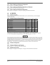
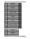
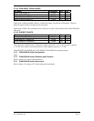
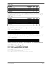
4.6.2.2 ARINC 429
Pin Name Connector Pin I/O
GPS ARINC 429 OUT A P5001 46 Out
GPS ARINC 429 OUT B P5001 47 Out
GPS ARINC 429 IN 1 A P5001 48 In
GPS ARINC 429 IN 1 B P5001 49 In
GPS ARINC 429 IN 2 A P5001 50 In
GPS ARINC 429 IN 2 B P5001 51 In
VOR/ILS ARINC 429 OUT A P5006 24 Out
VOR/ILS ARINC 429 OUT B P5006 23 Out
VOR/ILS ARINC 429 IN A P5006 36 In
VOR/ILS ARINC 429 IN B P5006 35 In
The GPS and VOR/ILS ARINC 429 outputs conform to ARINC 429 electrical specifications when loaded
with up to 5 standard ARINC 429 receivers.
4.6.3 Serial Data Configuration
Refer to section 5.2.1 for the main (GPS) ARINC 429 configuration. Refer to sections 5.2.13, 5.2.14, and
5.2.15 for the Stormscope configuration. Refer to section 5.2.16 for the Skywatch configuration. Refer to
sections 5.2.16 and 5.2.17 for the TCAD configuration. If the GDL 49 satellite data link transceiver has
been installed, refer to the GDL 49 Installation Manual (190-00231-00) for Configuration Mode
Operations.
4.6.4 Serial Data Calibration and Checkout
Refer to section 5.3.2 for the serial data checkout. Refer to sections 5.2.13, 5.2.14, and 5.2.15 for the
Stormscope checkout. Refer to section 5.2.16 for the Skywatch checkout. Refer to sections 5.2.16 and
5.2.17 for the TCAD checkout.
4.6.5 Serial Data Interconnect
Refer to Figure 4-10 on page 4-39 for the RS-232 serial data interconnect. Refer to Figure 4-11 on page 4-
41 for the ARINC 429 Bendix/King EFS 40/50 interconnect. Refer to Figures 4-12, 4-13 and 4-14 starting
on page 4-43 for the ARINC 429 Sandel EHSI interconnect. Refer to Figure 4-15 on page 4-49 for the
ARINC 429 air data/IRU/AHRS interconnect. Refer to Figure 4-16 on page 4-51 for the ARINC 429
flight control interconnect. Refer to Figure 4-17 on page 4-53 for the Traffic Advisory System
Interconnect, and Figure 4-18 on page 4-55 for the Weather and Terrain Interconnect.