


Page 3-4 500 SERIES INSTALLATION MANUAL
Rev G P/N 190-00181-02
3.6 CABLE INSTALLATION
1. Route the coaxial cable to the rack location keeping in mind the recommendations of Section 2.
Secure the cable in accordance with good aviation practice.
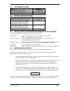
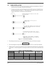
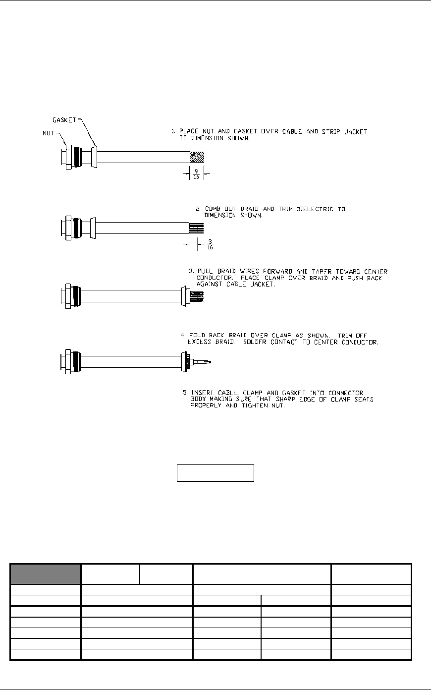
2. Trim the coaxial cable to the desired length and install the BNC connector (330-00087-00) per
the cabling instructions on Figure 3-1. If the connector is provided by the installer, follow the
connector manufacturer’s instructions for cable preparation.
Figure 3-1. Coaxial Cable Installation
3. The card-edge connector may be used to terminate shield grounds to the 500 Series back plate.
CAUTION
4. Feed wires through the connector backshells before insertion into the 78, 44, and 25 pin connectors.
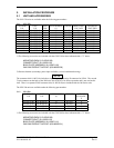
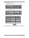
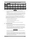
5. Contacts for the 78, 44 and 25 pin connectors must be crimped onto the individual wires of the aircraft
wiring harness. The following tables list contact part numbers (for reference) and recommended crimp
tools:
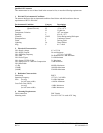
Table 3-1. Pin Contact Part Numbers
78 pin conn
(P5001/5008)
44 pin conn
(P5006)
25 pin connector (P5002) Shield ground
connector
Connector Type High Density Pin Contact Standard Density Socket Contact .1” Pitch Card-edge
Wire Gauge 22-24 AWG 18 AWG 20-24 AWG 20-24 AWG
Garmin P/N 336-00021-00 336-00023-00 336-00022-00 336-00029-00
Military P/N M39029/58-360 N/A M39029/63-368 N/A
AMP 204370-2 N/A 205090-1 583853-4
Positronic M39029/58-360 FC6018D M39029/63-368 N/A
ITT Cannon 030-2042-000 See Note 3 031-1007-042 N/A