


Page 4-6 500 SERIES INSTALLATION MANUAL
Rev G P/N 190-00181-02
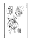
4.2.3 Power, Lighting, and Antennas Configuration
Refer to section 5.2.5 for lighting configuration.
4.2.4 Power, Lighting, and Antennas Calibration and Checkout
Refer to section 3.9 for the COM antenna checkout.
4.2.5 Power, Lighting, and Antennas Interconnect
Refer to Figure 4-4 on page 4-27 for the power, lighting, and antennas interconnect.
4.3 ALTIMETER
4.3.1 Altimeter Function
Altitude input is required for GPS RAIM calculations, and is useful for advisory vertical navigation
(VNAV) calculations.
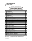
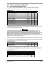
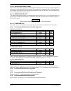
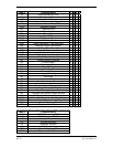
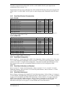
4.3.2 Altimeter Electrical Characteristics
Pin Name Connector Pin I/O
ALTITUDE D4 P5001 70 In
ALTITUDE A1 P5001 69 In
ALTITUDE A2 P5001 68 In
ALTITUDE A4 P5001 67 In
ALTITUDE B1 P5001 66 In
ALTITUDE B2 P5001 65 In
ALTITUDE B4 P5001 64 In
ALTITUDE C1 P5001 63 In
ALTITUDE C2 P5001 62 In
ALTITUDE C4 P5001 61 In
ALTITUDE COMMON P5001 60 In
These inputs are considered active if either the voltage to ground is <1.9 V or the resistance to ground
is <375 Ω. These inputs are considered inactive if the voltage to ground is 11-33 Vdc.
NOTE
Some transponders and other altitude encoder receivers do not have internal isolation diodes to prevent the
unit from pulling the encoder lines to ground when the unit is off. These units require a diode added to the
installation harness for each encoder line. The anode should be connected on the receiving unit’s side and
the cathode should be connected on the encoder side. A set of diodes is required for each unit without
internal diodes. The 500 Series unit includes internal diodes for isolation of the encoder lines.
4.3.3 Altimeter Configuration
None.
4.3.4 Altimeter Calibration and Checkout
Refer to section 5.2.7 for the gray code altitude checkout.
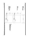
4.3.5 Altimeter Interconnect
Refer to Figure 4-2 on page 4-23 and Figure 4-5 on page 4-29 for the altimeter interconnect.