


Page 2-2 500 SERIES INSTALLATION MANUAL
Rev G P/N 190-00181-02
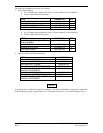
2.2.6 ANTENNA LIMITATIONS
Garmin’s GA 56 Antennas are recommended for installations where the airspeed of the aircraft is subsonic.
In such installations, GA 56—Mod 1 or later—must be used. See the COM, VOR/LOC, and Glideslope
antenna specifications for their limitations.
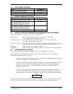
2.2.7 VHF COM INTERFERENCE OF GPS
On many panel-mounted installations, VHF COM transceivers can radiate strong harmonics from the
transceiver and its antenna. The 500 Series COM does not interfere with its own GPS section. However,
placement of the GA 56 GPS antenna relative to a COM transceiver and COM antenna, including the GNS
530 COM antenna, is critical.
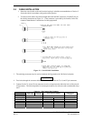
Use the following guidelines, in addition to others in this document, when locating the 500 Series unit and
its antennas.
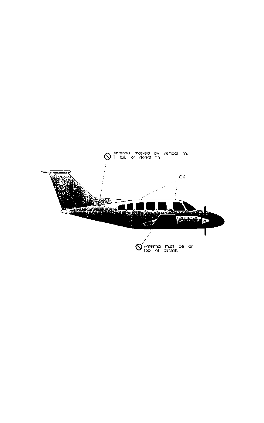
• GPS Antenna—Locate as far as possible from all COM antennas and all COM transceivers
(including the 500 Series COM). The GPS antenna i much less sensitive to COM antennas that
use a 1.57542 GHz notch filter.
• Locate the 500 Series unit as far as possible from all COM antennas.
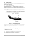
Figure 2-1. GPS Antenna Installation Considerations
If a COM antenna is found to be the problem, a 1.57542 GHz notch filter (Garmin P/N 330-00067-00) may
be installed in the VHF COM coax, as close to the COM as possible. This filter is not required for the
GNS 530 transmitter.
If a COM is found to be radiating, the following can be done:
1. Replace or clean VHF COM rack connector to ensure good coax ground.
2. Place a grounding brace between the 500 Series unit, VHF COM and ground.
3. Shield the VHF COM wiring harness.
2.2.8 COM, VOR/LOC, and Glideslope Antenna Installation Instructions
Install the COM, VOR/LOC, and Glideslope antennas according to the manufacturer’s recommendations.
Avoid running other wires and coaxial cables near the VOR/LOC antenna cable.