


500 SERIES INSTALLATION MANUAL Page 4-17
P/N 190-00181-02 Rev G
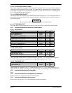
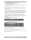
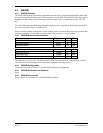
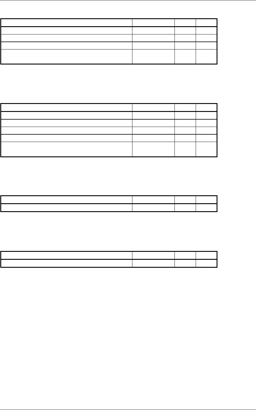
4.8.2.4 Flag
Pin Name Connector Pin I/O
VOR/LOC +FLAG P5006 3 Out
VOR/LOC -FLAG (VOR/LOC COMMON) P5006 4 Out
GLIDESLOPE +FLAG P5006 30 Out
GLIDESLOPE +DOWN/-FLAG (GLIDESLOPE
COMMON)
P5006 31 Out
The Flag output is capable of driving up to three 1000 Ω meter loads. When valid information is present
(Flag OUT OF VIEW) the Flag output is 375 ±80 mVdc
.
When invalid information is present (Flag IN
VIEW) the Flag output is 0 ±25 mVdc
.
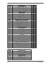
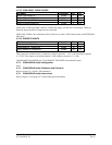
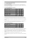
4.8.2.5 OBS
Pin Name Connector Pin I/O
VOR OBS ROTOR C P5006 9 Out
VOR OBS ROTOR H (GROUND) P5006 10 Out
VOR OBS STATOR D P5006 13 In
VOR OBS STATOR F P5006 12 In
VOR OBS STATOR E/G (VOR/LOC
COMMON)
P5006 11 Out
VOR OBS ROTOR C and H are a buffered 500 Hz output that is intended to drive the OBS rotors. VOR
OBS STATOR D and VOR OBS STATOR F are each phase and amplitude shifted version of the VOR
ROTOR C output. Each pair is intended to read one of the two windings of the indicator’s OBS stator.
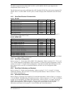
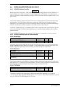
4.8.2.6 VOR/LOC COMPOSITE
Pin Name Connector Pin I/O
VOR/LOC COMPOSITE OUT P5006 8 Out
With a Standard VOR Test Signal applied, VOR/LOC COMPOSITE OUT is 0.5 ± 0.1 V
RMS
into a 10 kΩ
load. With a Standard Localizer Centering Test Signal applied, VOR/LOC COMPOSITE OUT is 0.350
±0.05 Vrms into a 10 kΩ load.
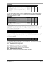
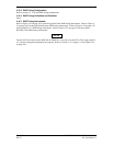
4.8.2.7 ILS ENERGIZE
Pin Name Connector Pin I/O
ILS ENERGIZE P5006 29 Out
The driver output voltage is not more than 1.0 V when sinking 20 mA. The maximum off state leakage
current with respect to GND is less than 10 µA.
4.8.3 VOR/ILS Indicator Configuration
Refer to section 5.2.11 for the VOR/LOC/GS configuration.
4.8.4 VOR/ILS Indicator Calibration and Checkout
Refer to sections 5.2.11 and 5.3.8 for the VOR/LOC/GS checkout.
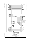
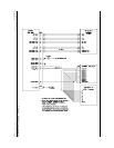
4.8.5 VOR/ILS Indicator Interconnect
Refer to Figure 4-20 on page 4-59 for the VOR/ILS indicator interconnect.