


Page 4-16 500 SERIES INSTALLATION MANUAL
Rev G P/N 190-00181-02
4.8 VOR/ILS INDICATOR (GNS 530 ONLY)
4.8.1 VOR/ILS Indicator Function
NOTE
Because the GNS 530 includes a “CDI” button that performs switching between GPS and VOR/ILS on a
remote indicator, it is seldom necessary to use these outputs to drive an indicator. It is only necessary
when it is desired for a separate indicator to display VOR/ILS deviation full-time (regardless of the “CDI”
button status).
The VOR/ILS indicator displays both lateral and vertical, To/From indications, lateral and vertical flags
and superflags. GNS 530 connector 5006 always outputs the VOR/Localizer/Glideslope navigation
information. The VOR/ILS pins on GNS 530 connector 5006 are used to drive an indicator that displays
VOR/ILS information at all times, regardless of the CDI selection on the GNS 530.
VOR/LOC COMPOSITE OUT is a standard VOR/Localizer Composite output signal which may be used
to drive the Left/Right, TO/FROM, and Flag indications of certain navigation indicators that contain an
internal converter.
The ILS ENERGIZE output goes low when the VLOC frequency is channeled to a localizer channel.
4.8.2 VOR/ILS Indicator Electrical Characteristics
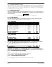
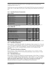
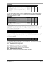
4.8.2.1 Superflags
Pin Name Connector Pin I/O
VOR/LOC SUPERFLAG P5006 15 Out
GLIDESLOPE SUPERFLAG P5006 38 Out
The output supplies not less than 500 mA on a 28 volt system and 250 mA on a 14 volt system with the
output voltage not less than (AIRCRAFT POWER -3 Vdc) when the flag is to be OUT OF VIEW. The
output voltage with respect to ground is less than 3 Vdc when the flag is to be IN VIEW.
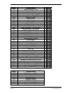
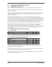
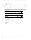
4.8.2.2 Deviation
Pin Name Connector Pin I/O
VOR/LOC +LEFT P5006 5 Out
VOR/LOC +RIGHT (VOR/LOC COMMON) P5006 6 Out
GLIDESLOPE +UP P5006 32 Out
GLIDESLOPE +DOWN/-FLAG (GLIDESLOPE
COMMON)
P5006 31 Out
The deviation outputs are each capable of driving up to three 1000 Ω meter loads with ±150 mVdc ±10%
with respect to 2.5V Common for full-scale deflection. The drive circuit provides for more than full-scale
deflection with a maximum course deviation output voltage of ±300 mVdc ±10%.
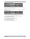
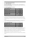
4.8.2.3 TO/FROM
Pin Name Connector Pin I/O
VOR/LOC +TO P5006 1 Out
VOR/LOC +FROM (VOR/LOC COMMON) P5006 2 Out
The output is capable of driving up to three 200 Ω meter loads. When indicating TO, the output is
+225 ±75 mVdc
.
When indicating FROM, output is -225 ±75 mVdc
.
When invalid information is present
(Flag IN VIEW) the TO/FROM output is 0 ±10 mVdc
.