


500 SERIES INSTALLATION MANUAL Page 3-5
P/N 190-00181-02 Rev G
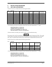
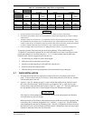
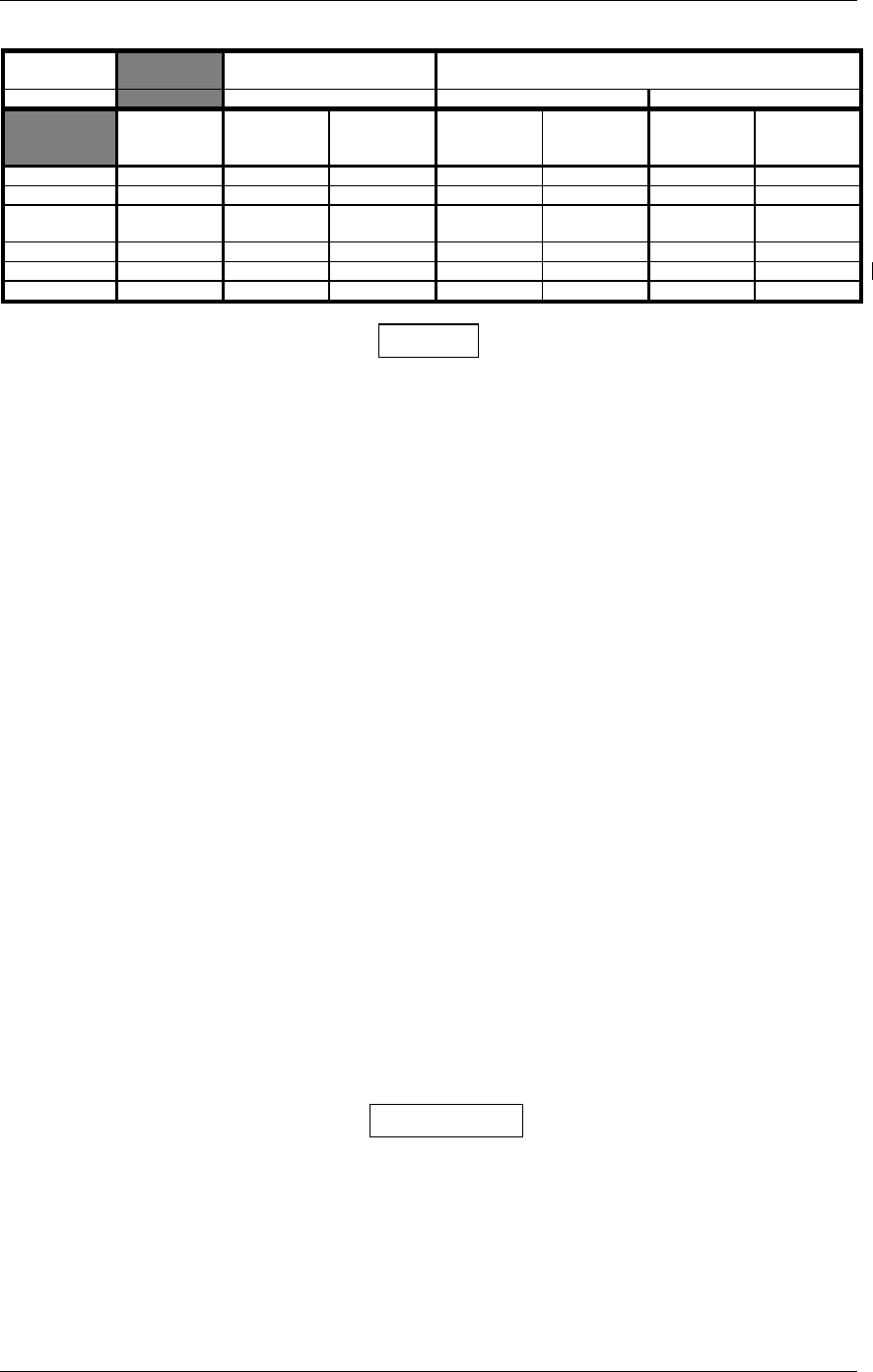
Table 3-2. Recommended Crimp Tools (or equivalent)
Connector
Type
High Density Standard Density
Wire Gauge 22-24 AWG 18 AWG 20-24 AWG
Hand
Crimping
Tool
Positioner Insertion/
Extraction
Tool
Positioner Insertion/
Extraction
Tool
Positioner Insertion/
Extraction
Tool
Military P/N M22520/2-01 M22520/2-09 M81969/1-04 N/A M81969/1-02 M22520/2-08 M81969/1-02
Positronic 9507 9502-3 M81969/1-04 9502-11 M81969/1-02 9502-5 M81969/1-02
ITT Cannon 995-0001-
584
995-0001-
739
N/A N/A N/A 995-0001-
604
980-2000-
426
AMP 601966-1 601966-6 91067-1 N/A N/A 601966-5 91067-2
Daniels AFM8 K42 M81969/1-04 K774 M81969/1-02 K13-1 M81969/1-02
Astro 615717 615725 M81969/1-04 N/A M81969/1-02 615724 M81969/1-02
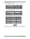
NOTES
1. Insertion/extraction tools from ITT Cannon are all plastic; others are plastic with metal tip.
2. Non-Garmin part numbers shown are not maintained by Garmin and consequently are subject to change
without notice.
3. Alternate contacts for 18 AWG wire: As an alternative to the Positronic contacts listed (and provided in
the installation kit), the installer may use contacts made by ITT Cannon under P/N 031-1007-001. These
contacts require the use of a different crimp tool positioner than shown in the table, with the part numbers
as follows: Daniels P/N K250, Astro P/N 616245, or ITT Cannon P/N 980-0005-722.
4. For the card-edge connector pin contacts, use AMP part number 90272-1 or equivalent crimping tool.
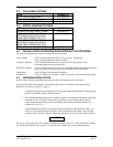
To prevent a possible short across the pins in the wiring harness, Teflon shrink tubing P/N
312-00005-05, provided in Connector Kit 011-00351-00 (P4002) covers the oversized power and
ground pin contacts P/N 336-00023-00 (pins 11, 12, 21, 22) that protrude from the back of the
connector shell. Before crimping the pins onto the wire:
1. Cut the tubing (312-00005-05) into 4 equal lengths.
2. Slide a short piece of the tubing over the wire.
3. Strip the wire and crimp the pin (336-00023-00) onto the wire.
4. Insert the pin into the connector shell.
5. Slide the tubing over the exposed portion of the pin and shrink using a heat gun.
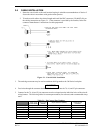
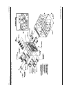
3.7 RACK INSTALLATION
1. The back plate of the rack may optionally be removed for ease of mounting in the aircraft
panel. To do so, remove the two #4-40 screws, tilt the back plate away from the tray, and then
slide the back plate to the side.
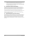
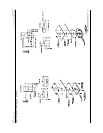
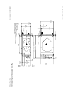
2. Figures 3-3 and 3-4, starting on page 3-9, shows outline dimensions for the aviation rack for
the various 500 Series units. Install the rack in a rectangular 6.320” x 4.600” hole (or gap
between units) in the instrument panel (refer to Figure 3-7, page 3-17). The lower-front lip of
the rack should be flush with, or extend slightly beyond, the finished aircraft panel.
CAUTION
If the front lip of the mounting rack is behind the surface of the aircraft panel, the 500 Series
unit connectors may not fully engage.
Make sure that no screw heads or other obstructions prevent the unit from fully engaging in the
rack (refer to the “Connector Engagement Test,” section 5.3.1, page 5-16). Exercise caution
when installing the rack into the instrument panel. The rack is designed to facilitate removal of
the 500 Series for use in Demo Mode outside the aircraft. Deformation of the rack may make it
difficult to install and remove the 500 Series unit.