


500 SERIES INSTALLATION MANUAL Page 5-11
P/N 190-00181-02 Rev G
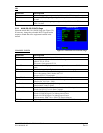
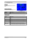
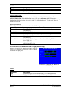
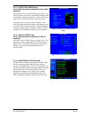
5.2.10 VOR DISCRETE INPUTS Page
(GNS 530 Only)
Select the VOR DISCRETE INPUTS Page (see Figure 5-
11). This page allows you to verify the operation of an
external VLOC transfer switch that may be present in the
installation.
Selection Verify That:
REMOTE XFR
The box is filled in while a remote VLOC transfer switch is pressed.
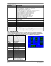
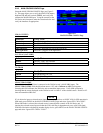
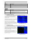
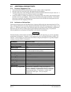
5.2.11 VOR/LOC/GS CDI Page (GNS 530 Only)
Select the VOR/LOC/GS CDI Page (see Figure 5-12).
This page allows you to verify and calibrate the CDI
outputs,
both lateral (LAT) and vertical (VERT) from the
VOR/LOC/Glideslope receiver, as well as the OBS
resolver input to the VOR receiver. It also allows you to
select the format for DME tuning data. Using the controls
on the GNS 530 front panel, make the selections below
and verify the interfaces as appropriate:
NOTE
The LAT, VERT, and SELECTED COURSE configurations only apply to installations where a CDI/HSI is
connected to the VOR/LOC/GLIDESLOPE pins on connector P5006.
CDI (LAT/VERT)
Selection Verify That:
Max left/up
The CDI is “pegged” to the left/up.
Full left/up
The CDI is deflected full scale to the left/up.
Center
The CDI is centered.
Full right/down
The CDI is deflected full scale to the right/down.
Max right/down
The CDI is “pegged” to the right/down.
FLAG (LAT/VERT)
Selection Verify That:
Hide
The LAT/VERT flag is hidden.
View
The LAT/VERT flag is in view.
S-FLG (LAT/VERT)
Selection Verify That:
Hide
The LAT/VERT superflag is hidden.
View
The LAT/VERT superflag is in view.
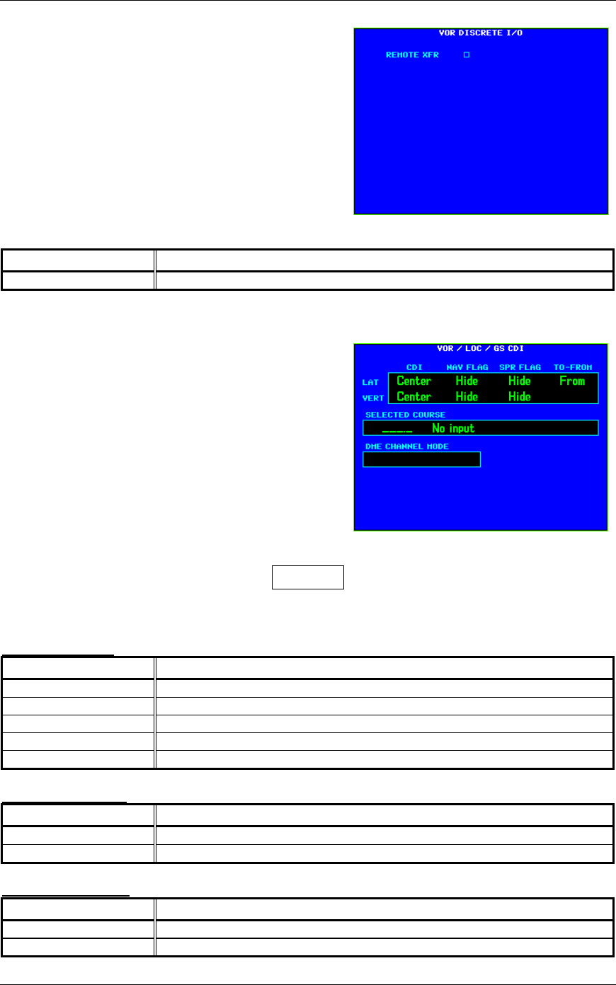
Figure 5-11.
VOR DISCRETE INPUTS Page
Figure 5-12.
VOR/LOC/GS CDI Page