


500 SERIES INSTALLATION MANUAL Page 4-7
P/N 190-00181-02 Rev G
4.4 MAIN INDICATOR
4.4.1 Main Indicator Function
The Main Indicator displays both lateral and vertical deviation from selected course, To/From indications,
lateral and vertical flags and superflags.
The “CDI” key on the bezel of the GNS 530 takes the place of remote “NAV/GPS” switches, and is used
to toggle between display of GPS and VOR/ILS navigation display on a remote indicator. The Navigation
source is annunciated on the display above the ‘CDI’ key. The Navigation method is optionally
annunciated externally by connecting to the VLOC ANNUNCIATE output (P5001-1) and GPS
ANNUNCIATE output (P5001-2). GPS and VOR/ILS navigation may be toggled externally when the
CDI SOURCE SELECT input (P5001-73) is momentarily grounded. See section 4.5 for more information
on the external annunciators and switches.
An OBS resolver connection to the GPS is preferred, but not required. For the GNS 530, an OBS resolver
typically is connected to the MAIN OBS inputs for use with the GNS 530 VOR receiver.
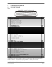
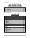
4.4.2 Main Indicator Electrical Characteristics
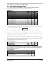
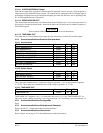
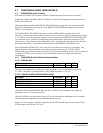
4.4.2.1 Deviation
Pin Name Connector Pin I/O
MAIN +LEFT P5001 21 Out
MAIN +RIGHT (2.5V COMMON) P5001 22 Out
MAIN +UP P5001 27 Out
MAIN +DOWN (2.5V COMMON) P5001 28 Out
The deviation output is capable of driving up to three 1000 Ω meter loads with ±150 mVdc ±10% for full-
scale deflection. The drive circuit provides for more than full-scale deflection with a maximum course
deviation output voltage of ±300 mVdc ±10%
.
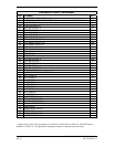
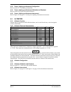
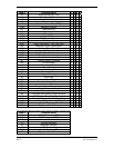
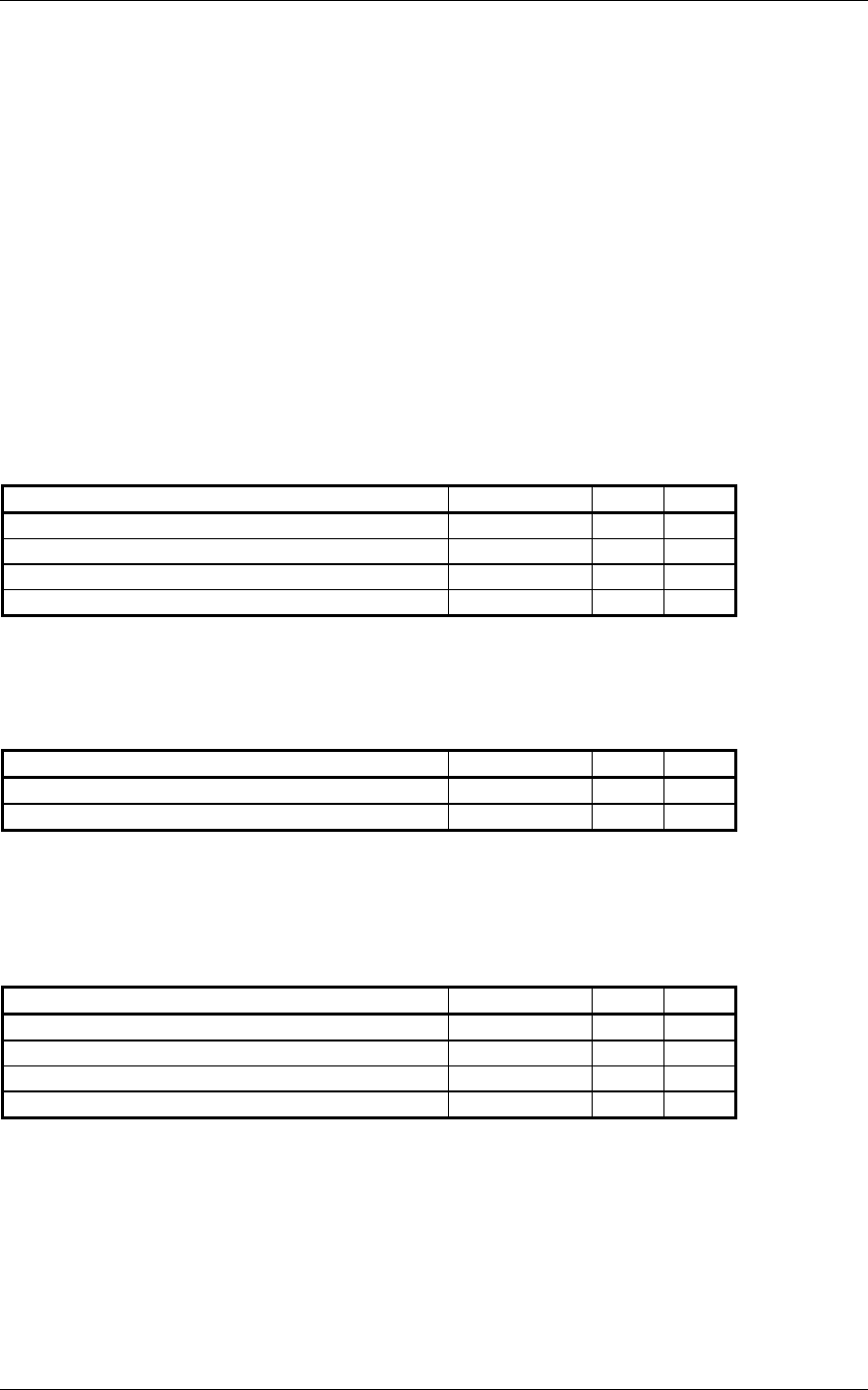
4.4.2.2 TO/FROM
Pin Name Connector Pin I/O
MAIN +TO P5001 25 Out
MAIN +FROM (2.5V COMMON) P5001 26 Out
The output is capable of driving up to three 200 Ω meter loads. When indicating TO, MAIN +TO is
+190 ±40 mVdc with respect to MAIN +FROM. When indicating FROM, MAIN +TO is -190 ±40 mVdc
with respect to MAIN +FROM. When invalid information is present (Flag IN VIEW) the TO/FROM
output is 0 ±10 mVdc
.
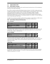
4.4.2.3 Flag
Pin Name Connector Pin I/O
MAIN LATERAL +FLAG P5001 23 Out
MAIN LATERAL -FLAG (2.5V COMMON) P5001 24 Out
MAIN VERTICAL +FLAG P5001 29 Out
MAIN VERTICAL -FLAG (2.5V COMMON) P5001 30 Out
The Flag output is capable of driving up to three 1000 Ω meter loads. When valid information is present
(Flag OUT OF VIEW) the Flag output is 375 ±80 mVdc
.
When invalid information is present (Flag IN
VIEW) the Flag output is 0 ±25 mVdc
.