


500 SERIES INSTALLATION MANUAL Page 5-7
P/N 190-00181-02 Rev G
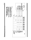
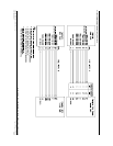
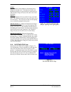
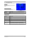
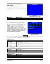
5.2.7 MAIN DISCRETE I/O Page
Select the MAIN DISCRETE I/O Page (see Figure 5-8).
GRAY CODE
If the encoding altimeter input is used, verify that the
DECODED ALTITUDE field indicates the correct
altitude.
EXTERNAL SWITCH STATE
This allows you to verify the operation of any external
switches that are present in the installation.
Selection Verify That:
RMT CDI
The box is filled in while a remote CDI source select switch is pressed.
RMT OBS
The box is filled in while a remote OBS switch is pressed.
DISCRETE TOGGLE
This allows you to verify the operation of any external annunciators that are present in the installation.
Selection Verify That:
APR
The APR annunciator is active and inactive as selected on this page.
GPS
The GPS source select annunciator is active and inactive as selected on this
page.
INTEG
The INTEG annunciator is active and inactive as selected on this page.
MSG
The MSG annunciator is active and inactive as selected on this page.
OBS
The OBS annunciator is active and inactive as selected on this page.
TERM
The TERM annunciator is active and inactive as selected on this page.
VLOC
The VLOC source select annunciator is active and inactive as selected on this
page.
WPT
The WPT annunciator is active and inactive as selected on this page.
ILS/GPS APR
The ILS/GPS APPROACH output is active and inactive as selected on this
page (NOTE: This output is connected to the autopilot ILS ENGAGE input,
not to an annunciation, and therefore this is for bench testing purposes only).
Figure 5-8.
MAIN DISCRETE I/O Page