


Page 5-6 500 SERIES INSTALLATION MANUAL
Rev G P/N 190-00181-02
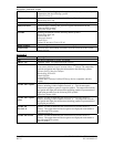
SLOPE
Sets the sensitivity the brightness of the display has to
changes in the input level. The higher the number, the
brighter the display for a given increase in the input level.
This field has a range of 0 (zero) to 99, and is set to 50 at
the factory.
OFFSET
Adjusts the lighting level up or down for any given input
level. This field has a range of 0 (zero) to 99, and is set to
50 at the factory. This may also be used to match lighting
curves with other equipment in the panel.
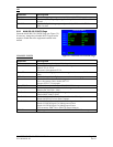
PHOTO TRANS % - (Photocell Transition Percentage)
When a lighting bus is used to control the lighting of the
display (see Figure 5-6), this parameter sets the point on
the lighting bus control below which the display brightness
tracks the 500 Series unit’s photocell. This field has a
range of 0 (zero) to 99, and is set to 25 at the factory.
PHOTO SLP/OFFST - (Photocell Slope/Offset)
These fields are equivalent to the SLOPE/OFFSET fields
described above, with the exception that they only control
the display lighting characteristics when the lighting bus
control is below the level specified in the PHOTO TRANS
% field. Both fields have a range of 0 (zero) to 99, and are
set to 50 at the factory.
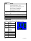
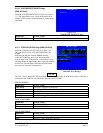
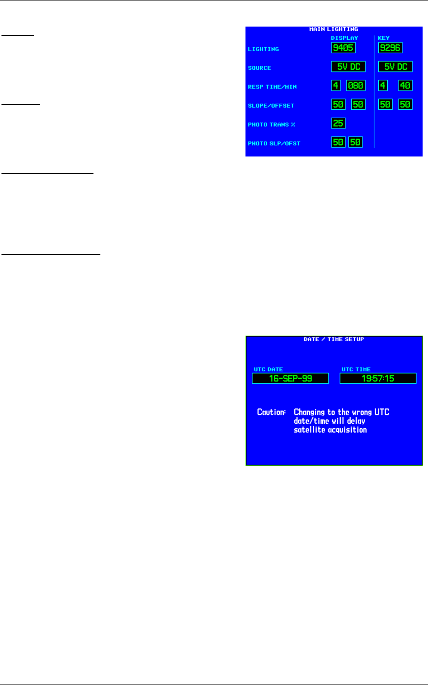
5.2.6 DATE/TIME SETUP Page
Select the DATE/TIME SETUP Page (see Figure 5-7).
Very infrequently, it may be desirable to set the date and
time of the 500 Series unit to aid in acquiring a GPS
position. Configuration mode is the only means by which
the date and time for the 500 Series unit may be adjusted.
Note that the time must be UTC time, and that the UTC
date may be different from the date in the local time zone.
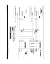
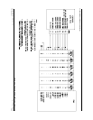
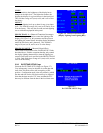
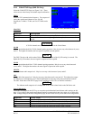
Figure 5-6. MAIN LIGHTING Page
(Display Lighting from Lighting Bus)
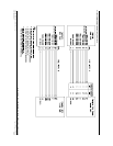
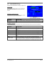
Figure 5-7.
DATE/TIME SETUP Page