


500 SERIES INSTALLATION MANUAL Page 5-5
P/N 190-00181-02 Rev G
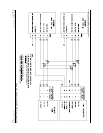
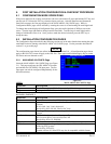
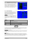
5.2.4 INSTRUMENT PANEL SELF-TEST Page
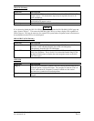
Select the INSTRUMENT PANEL SELF-TEST Page (see
Figure 5-4). This page allows verification that the 500
Series unit is communicating properly with other
instruments. Compare on-screen indications with the
information depicted on connected instruments, such as the
CDI, HSI, RMI and/or external annunciators. It also
displays fuel capacity, amount on-board, and flow.
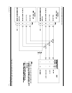
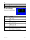
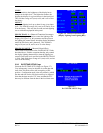
5.2.5 MAIN LIGHTING Page
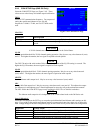
Select the MAIN LIGHTING Page (see Figure 5-5). This
page allows you to set display parameters that affect the
display backlight and key lighting brightness. The
DISPLAY and KEY lighting characteristics are adjusted
separately, each with the following fields:
LIGHTING
Shows the current level of display backlighting, based on
the lighting input source (lighting bus voltage, or the
ambient light if the source is PHOTO) and the settings on
this configuration page. This field has a range of 0 (zero)
to 9999.
Figure 5-5. MAIN LIGHTING PAGE
SOURCE
Selection Description
PHOTO
Backlight level is determined by the ambient light level as measured by the
photocell on the 500 Series unit.
14V DC
Backlight level tracks a 14 volt DC aircraft lighting bus.
28V DC
Backlight level tracks a 28 volt DC aircraft lighting bus.
5V DC
Backlight level tracks a 5 volt DC aircraft lighting bus.
5V AC
Backlight level tracks a 5 volt AC aircraft lighting bus.
If a lighting bus (any selection other than PHOTO) is selected, and the lighting bus control is turned to its
minimum (daytime) setting, the display brightness tracks the 500 Series unit’s photocell using additional
parameters (PHOTO TRANS % and PHOTO SLP/OFFST) described below.
RESP TIME - (Response Time)
Sets the speed with which the brightness responds to the input level (bus voltage or ambient light) changes.
The higher the number the slower the display responds. This field has a range of 3 to 7, and is set to 4 at
the factory.
MIN - (Minimum)
Sets the minimum brightness of the display. The higher the number, the brighter the minimum brightness.
Display minimum brightness has a range of 35 to 999, and is set to 80 at the factory. Key minimum
brightness has a range of 20 to 99, and is set to 40 at the factory. It is prudent to verify that display and key
lighting characteristics match those of other equipment in the panel under night lighting conditions.
Figure 5-4. INSTRUMENT PANEL
SELF-TEST Page
NOTE