


500 SERIES INSTALLATION MANUAL Page 3-1
P/N 190-00181-02 Rev G
3. INSTALLATION PROCEDURE
3.1 UNIT AND ACCESSORIES
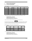
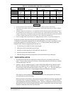
The GNS 530 units are available under the following part numbers:
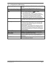
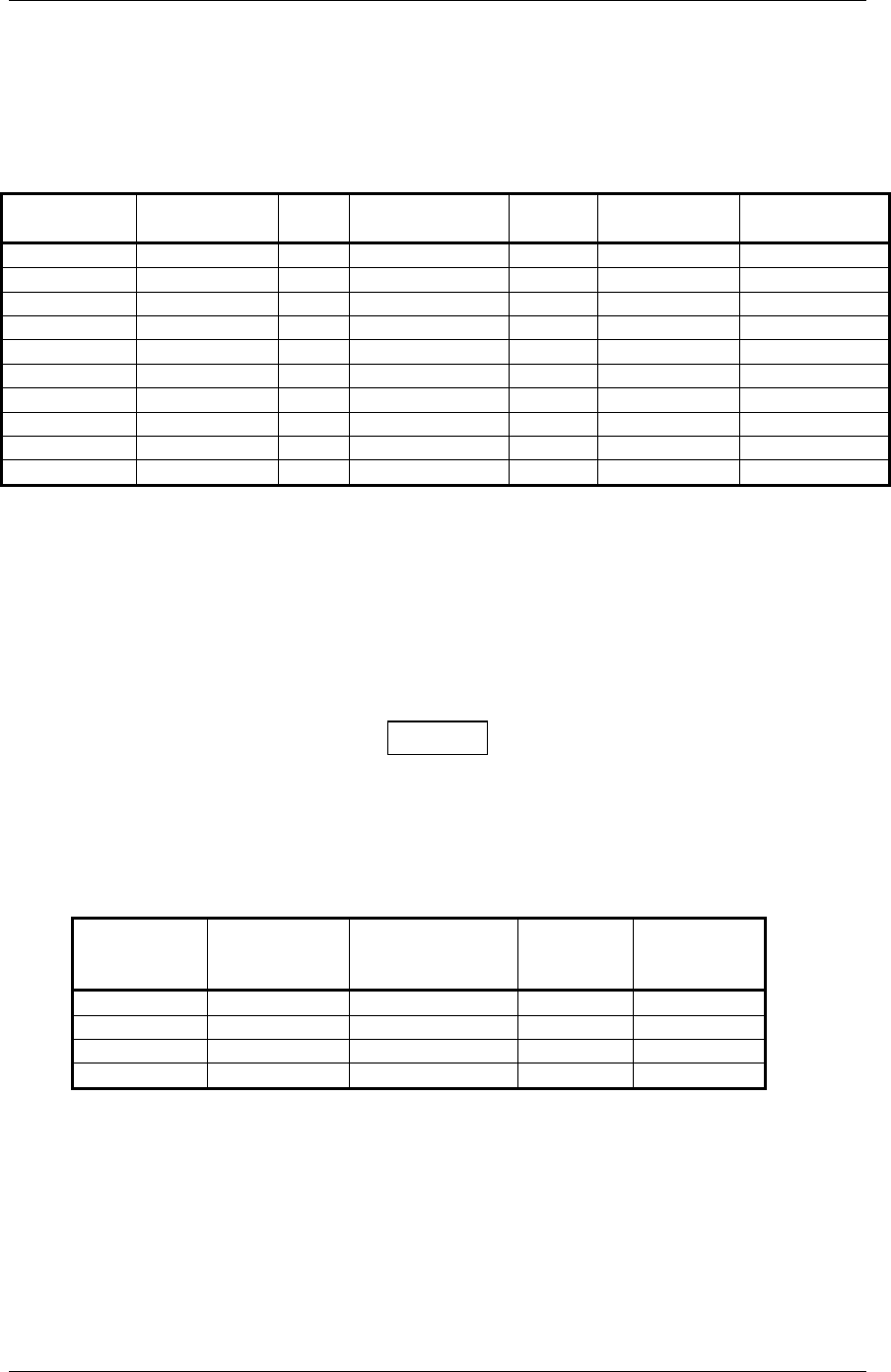
3.1.1 GNS 530
CATALOG
P/N
UNIT
P/N
GNS
530A
ACCESSORIES
(1)
COLOR OPERATING
VOLTAGE
MINIMUM
XMIT PWR
010-00182-00 011-00550-00 N N BLACK 28 10 W
010-00182-01 011-00550-00 N Y BLACK 28 10 W
010-00182-10 011-00550-10 N N BLACK 14 or 28 Vdc 10 W
010-00182-11 011-00550-10 N Y BLACK 14 or 28 Vdc 10 W
010-00182-30 011-00550-30 N N GRAY 14 or 28 V (2) 10 W
010-00182-31 011-00550-30 N Y GRAY 14 or 28 V (2) 10 W
010-00285-00 011-00835-00 Y N BLACK 28 Vdc 16 W
010-00285-01 011-00835-00 Y Y BLACK 28 Vdc 16 W
010-00285-10 011-00835-10 Y N GRAY 28 Vdc (2) 16 W
010-00285-11 011-00835-10 Y Y GRAY 28 Vdc (2) 16 W
1) The following accessories are included with the GNS 530 for those indicated with a “Y” above:
MOUNTING RACK (115-00345-00)
CONNECTOR KIT (011-00351-00)
BACK PLATE ASSEMBLY (011-00671-00)
GNS 530 PRODUCT INFO KIT (K00-00060-00)
2) Denotes alternate (secondary) power input available, (review installation drawing).
NOTE
The connector kit 011-00351-0x includes a single 78-pin high-density D connector for P5001. The second
78-pin connector on the back of the 500 Series unit (P5050) is for future expansion and is not used at this
time. There is a separate P5050 connector kit (011-00558-00) not included with the 500 Series units.
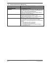
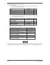
The GPS 500 units are available under the following part numbers:
3.1.2 GPS 500
CATALOG
P/N
UNIT
P/N
ACCESSORIES
(1)
COLOR ALT PWR
AVAILABL
E
010-00176-00 011-00562-00 N BLACK N
010-00176-01 011-00562-00 Y BLACK N
010-00176-10 011-00562-10 N GRAY Y
010-00176-11 011-00562-10 Y GRAY Y
1) The following accessories are included with the GNS 500 for those indicated with a “Y” above:
MOUNTING RACK (115-00345-00)
CONNECTOR KIT (011-00351-03)
BACK PLATE ASSEMBLY (011-00671-01)
GNS 500 PRODUCT INFO KIT (K00-00060-01)