


500 SERIES INSTALLATION MANUAL Page 4-15
P/N 190-00181-02 Rev G
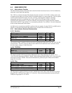
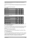
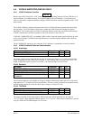
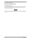
4.7.2.3 COM AUDIO, VOR/ILS AUDIO
Pin Name Connector Pin I/O
500Ω COM AUDIO HI
P5002 7 Out
500Ω COM AUDIO LO
P5002 19 Out
500Ω VOR/ILS AUDIO HI
P5006 16 Out
500Ω VOR/ILS AUDIO LO
P5006 17 Out
500Ω COM AUDIO and 500Ω VOR/ILS AUDIO each supply 100 mW into a 500 Ω load. These are
balanced outputs and the LO output must be connected.
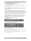
500Ω COM AUDIO is the summation of the COM receiver audio, COM sidetone audio, and INTERCOM
MIC audio.
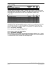
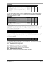
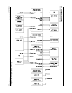
4.7.2.4 DISCRETE INPUTS
Pin Name Connector Pin I/O
TRANSMIT INTERLOCK P5002 14 In
COM REMOTE TRANSFER P5002 15 In
VLOC REMOTE TRANSFER P5006 28 In
These inputs are considered active if either the voltage to ground is <1.9 V or the resistance to ground
is <375 Ω. These inputs are considered inactive if the voltage to ground is 11-33 Vdc.
COM REMOTE TRANSFER and VLOC REMOTE TRANSFER are momentary inputs.
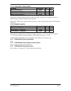
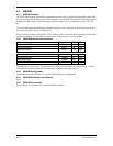
4.7.3 COM/VOR/ILS Audio Configuration
None.
4.7.4 COM/VOR/ILS Audio Calibration and Checkout
Refer to section 5.2.9 for the COM calibration.
4.7.5 COM/VOR/ILS Audio Interconnect
Refer to Figure 4-19 on page 4-57 for the audio panel interconnect.