


Page 3-6 500 SERIES INSTALLATION MANUAL
Rev G P/N 190-00181-02
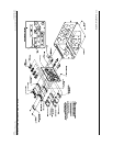
3. Install the rack in the aircraft panel using six #6-32 flat head screws and six self-locking nuts.
The screws are inserted from the inside through the holes in the sides of the rack.
4. If the back plate was previously removed (see step #1), replace the back plate by positioning
the tabs on the back plate in the slots of the left side of the rack (viewing it from the cockpit)
and attaching it by replacing the two #4-40 screws.
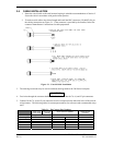
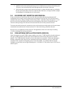
3.8 500 SERIES UNIT INSERTION AND REMOVAL
It may be necessary to insert the hex drive tool into the access hole and rotate the mechanism 90°
counterclockwise to insure correct position prior to placing the unit in the rack. The 500 Series unit is
installed in the rack by sliding it straight in until it stops, about 1 inch short of the final position. A 3/32”
hex drive tool is then inserted into the access hole at the bottom of the unit face. Rotate the hex tool
clockwise while pressing on the left side of the bezel until the unit is firmly seated in the rack.
To remove the unit from the rack, insert the hex drive tool into the access hole on the unit face and rotate
counterclockwise until the unit is forced out about 3/8” and can be freely pulled from the rack.
Be sure not to over tighten the unit into the rack. The application of hex drive tool torque exceeding
15 in•lbs can damage the locking mechanism.
3.9 COM ANTENNA INSTALLATION CHECK (GNS 530)
Check for insertion loss and VSWR (voltage standing wave ratio). VSWR should be checked with an in-
line type VSWR/wattmeter inserted in the coaxial transmission line between the transceiver and the
antenna. The VSWR should be inserted as close to the transceiver as possible. When rack and harness
buildup is performed in the shop, the coax termination may be provisioned by using a 6” inline BNC
connection. This would be an acceptable place to insert the VSWR. Any problem with the antenna
installation is most likely seen as high reflected power. A VSWR of 3:1 may result in up to a 50% loss in
transmit power.