


Page 4-8 500 SERIES INSTALLATION MANUAL
Rev G P/N 190-00181-02
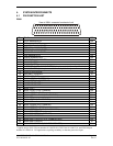
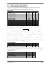
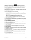
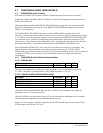
4.4.2.4 Superflags
Pin Name Connector Pin I/O
MAIN LATERAL SUPERFLAG P5001 17 Out
MAIN VERTICAL SUPERFLAG P5001 18 Out
The output supplies not less than 500 mA on a 28 volt system and 250 mA on a 14 volt system with the
output voltage not less than (AIRCRAFT POWER –1.5 Vdc) when the flag is to be OUT OF VIEW. The
output voltage with respect to ground is less than 0.25 Vdc when the flag is to be IN VIEW.
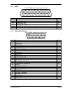
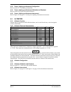
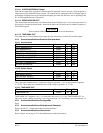
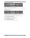
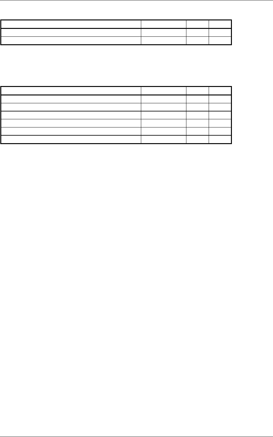
4.4.2.5 OBS
Pin Name Connector Pin I/O
MAIN OBS ROTOR C P5001 31 Out
MAIN OBS ROTOR H (GROUND) P5001 32 Out
MAIN OBS STATOR D P5001 33 In
MAIN OBS STATOR E (2.5V COMMON OBS) P5001 34 Out
MAIN OBS STATOR F P5001 35 In
MAIN OBS STATOR G (2.5V COMMON OBS) P5001 36 Out
MAIN OBS ROTOR C and H are a buffered output that is intended to drive the OBS rotors. MAIN OBS
STATOR D and MAIN OBS STATOR F are each phase and amplitude shifted version of the MAIN
ROTOR C output. Each pair is intended to read one of the two windings of the indicator’s OBS stator.
4.4.3 Main Indicator Configuration
Refer to section 5.2.8 for the main CDI/OBS configuration.
4.4.4 Main Indicator Calibration and Checkout
Refer to section 5.2.8 for the main CDI/OBS checkout.
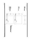
4.4.5 Main Indicator Interconnect
Refer to Figure 4-6 on page 4-31 for the generic main indicator interconnect. Refer to Figure 4-7 on page
4-33 for the interconnect between a GNS 530 and a Bendix/King KI 209A. Refer to Figure 4-8 on page 4-
35 for the interconnect between a GPS 500 and a Bendix/King KI 208A.