


2-15190-00601-02 Rev. B
Garmin G600 Pilot’s Guide
Foreword
Sec 1
System
Sec 2
PFD
Sec 3
MFD
Sec 4
Hazard
Avoidance
Sec 5
Additional
Features
Sec 6
Annun.
& Alerts
Sec 7
Symbols
Sec 8
Glossary Appendix A
Appendix B
Index
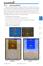
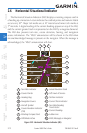
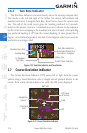
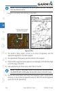
NOTE: The ILS Localizer and Glideslope deviation indicators will indicate
full scale deflection for the GNS 480 navigator at the second dot. The GNS
400W/500W series navigators will indicate full scale deflection at the edge
of the display.
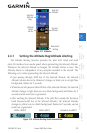
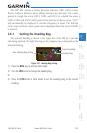
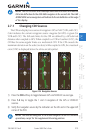
2.7.1 Changing CDI Sources
The CDI can display two sources of navigation: GPS or NAV (VOR, and LOC).
Color indicates the current navigation source: magenta (for GPS) or green (for
VOR and LOC). The full scale limits for the CDI are defined by a GPS-derived
distance when coupled to GPS. When coupled to a VOR or localizer (LOC), the
CDI has the same angular limits as a mechanical CDI. If the CDI exceeds the
maximum deviation on the scale (two dots) while coupled to GPS, the crosstrack
error (XTK) is displayed below the white aircraft symbol.
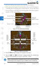
Figure 2-24 Navigation Sources
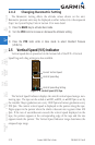
1) Press the CDI soft key to toggle between GPS and VOR/LOC source type.
2) Press 1-2 key to toggle the 1 and 2 navigators of the GPS or VOR/LOC
sources.
3) Verify the navigation source by the indication on the HSI and in the upper left
corner of the PFD.
NOTE: The selected navigator is the active navigator for all PFD and MFD
operations, except for the supplemental bearing pointers.