


2-6
Garmin G600 Pilot’s Guide
190-00601-02 Rev. B
Foreword
Sec 1
System
Sec 2
PFD
Sec 3
MFD
Sec 4
Hazard
Avoidance
Sec 5
Additional
Features
Sec 6
Annun.
& Alerts
Sec 7
Symbols
Sec 8
GlossaryAppendix A
Appendix B
Index
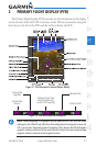
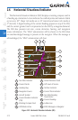
The horizon line is part of the pitch scale. Above and below the horizon line,
major pitch marks and numeric labels are shown for every 10°, up to 80°. Minor
pitch marks are shown for intervening 5° increments, up to 25° below and 45°
above the horizon line. Between 20° below to 20° above the horizon line, minor
pitch marks occur every 2.5°.
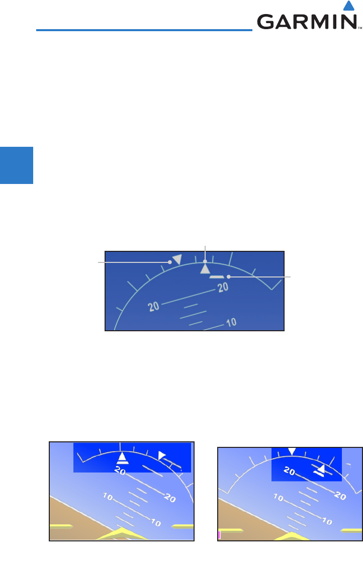
Major tick marks at 30° and 60° and minor tick marks at 10°, 20°, and 45°
are shown to the left and right of the zero. Angle of bank is indicated by the
position of the pointer on the roll scale.
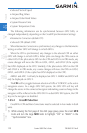
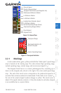
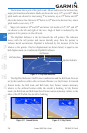
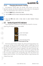
The Slip/Skid Indicator is the bar beneath the roll pointer. The indicator
moves with the roll pointer and moves laterally away from the pointer to
indicate lateral acceleration. Slip/skid is indicated by the location of the bar
relative to the pointer. One bar displacement (as shown below) is equal to one
ball displacement on a traditional Slip/Skid Indicator.
Roll Pointer
Slip/Skid Indicator
Roll Scale Zero
Figure 2-10 Slip/Skid Indication
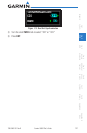
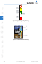
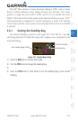
The Slip/Skid Indicator / Roll Pointer combination and the Roll Scale Zero are
set by the installer to reflect either a Ground Pointer or a Sky Pointer. In Ground
Pointer mode, the Roll Scale and Roll Scale Zero Pointer remain stationary
relative to the artificial horizon while the aircraft is banking. In Sky Pointer
mode, the Roll Scale and Roll Scale Zero Pointer remain stationary relative to the
sides of the PFD while the aircraft is banking.
Figure 2-11 Ground Pointer Figure 2-12 Sky Pointer