


ENGINE
3-5
▲▲▲▲▲▲▲▲▲▲▲▲▲▲▲▲▲▲▲▲▲▲▲▲▲▲▲▲▲▲
5. Adjust:
• Valve clearance
▼▼▼▼▼▼▼▼▼▼▼▼▼▼▼▼▼▼▼▼▼▼▼▼▼▼▼▼▼▼
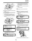
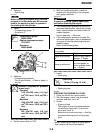
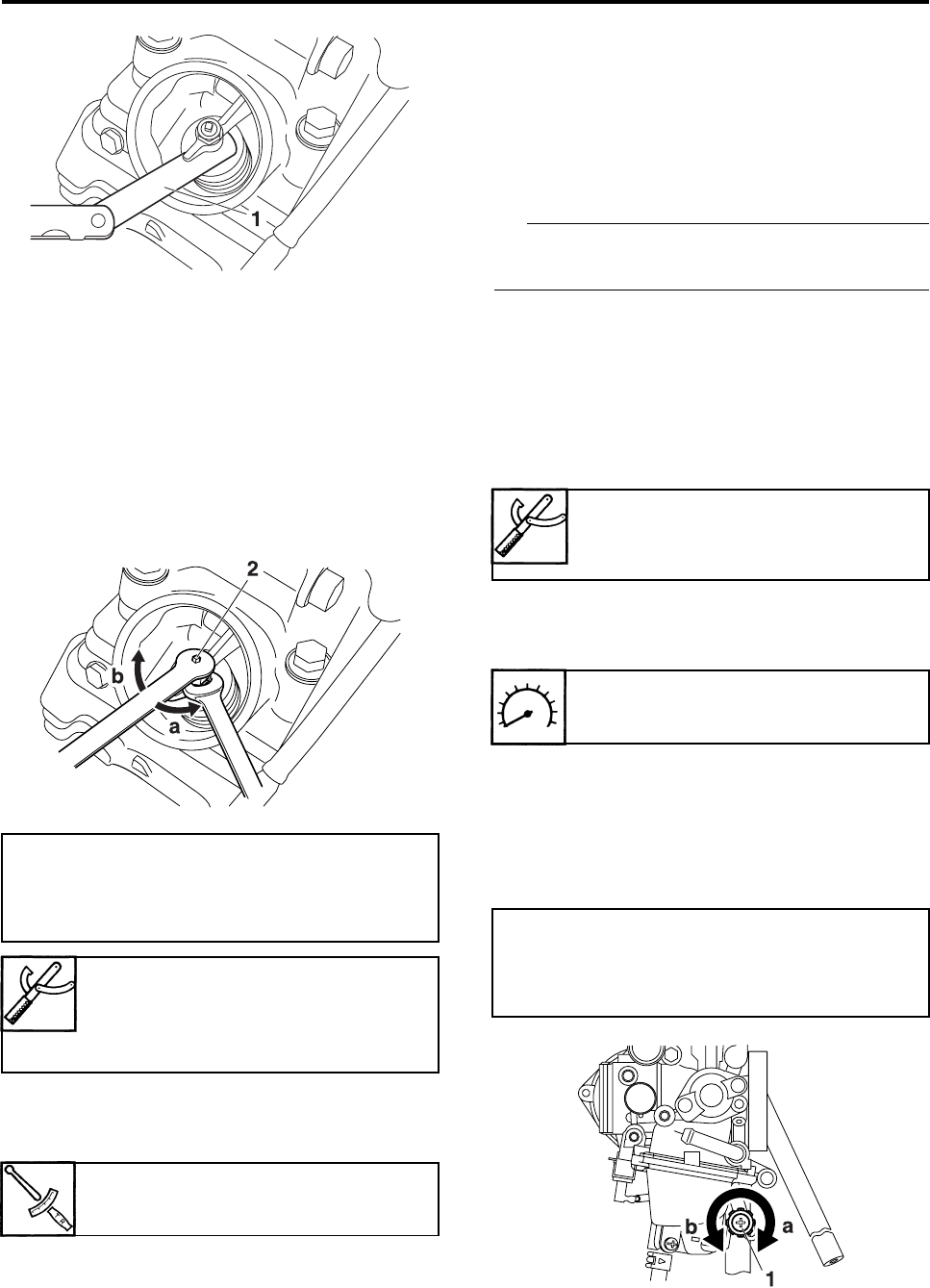
a. Loosen the locknut.
b. Insert a thickness gauge between the end
of the adjusting screw and the valve tip.
c. Turn the adjusting screw “2” in direction “a”
or “b” until the specified valve clearance is
obtained.
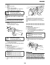
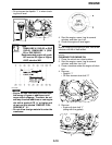
• Hold the adjusting screw to prevent it
from moving and tighten the locknut to
specification.
d. Measure the valve clearance again.
e. If the valve clearance is still out of specifi-
cation, repeat all of the valve clearance
adjustment steps until the specified clear-
ance is obtained.
▲▲▲▲▲▲▲▲▲▲▲▲▲▲▲▲▲▲▲▲▲▲▲▲▲▲▲▲▲▲
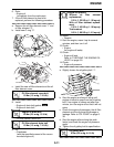
6. Install:
• All removed parts
TIP
For installation, reverse the removal proce-
dure.
EAS29150
ADJUSTING THE ENGINE IDLING SPEED
1. Start the engine and let it warm up for sev-
eral minutes.
2. Attach:
• Digital tachometer
(onto the ignition coil spark plug lead)
3. Measure:
• Engine idling speed
Out of specification → Adjust.
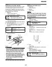
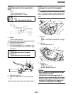
4. Adjust:
• Engine idling speed
▼▼▼▼▼▼▼▼▼▼▼▼▼▼▼▼▼▼▼▼▼▼▼▼▼▼▼▼▼▼
a. Turn the throttle stop screw “1” in direction
“a” or “b” until the specified idling speed is
obtained.
▲▲▲▲▲▲▲▲▲▲▲▲▲▲▲▲▲▲▲▲▲▲▲▲▲▲▲▲▲▲
Direction “a”
Valve clearance is increased.
Direction “b”
Valve clearance is decreased.
Tappet adjusting tool
90890-01311
Six piece tappet set
YM-A5970
Locknut
14 Nm (1.4 m·kg, 10 ft·lb)
Digital tachometer
90890-06760
YU-39951-B
Engine idling speed
1500–1600 r/min
Direction “a”
Engine idling speed is increased.
Direction “b”
Engine idling speed is decreased.