


CABLE ROUTING
2-40
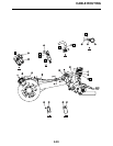
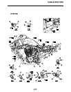
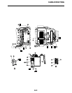
1. Indicator light
2. Coupler joint
3. Main switch lead
4. Main switch
5. Front brake light switch lead
6. Throttle cable
7. Air vent hose
8. Clutch switch lead
9. Handlebar switch lead
10.Parking brake cable
11.Clutch cable
12.Flange bolt
13.Headlight lead
14.Indicator light lead
15.Rear brake reservoir
16.Rear brake light switch lead
17.Battery negative lead
18.Carburetor warmer lead
19.Starter motor lead
20.Rectifier/regulator
21.Main harness
22.Frame complete
23.Clamp
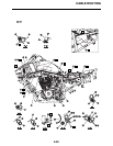
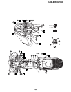
A. Install the indicator light as shown in the
illustration.
B. Place the coupler joint above the front
fender.
C. Connect the main switch lead on top of the
front fender. Route both leads from the
front.
D. Route the front brake light switch lead and
throttle cable through the guide.
E. Insert the air vent hose into the front
fender.
F. Route the clutch switch lead and handlebar
switch lead on the box shaped part.
G. Connect the clutch switch lead and handle-
bar switch lead on top of the front fender.
Route the wire harness from the front.
H. Route the cables and leads through the
guide of the front fender. Route the leads
behind the clutch and parking brake cable.
I. Route the headlight lead under the frame.
J. To the front fender
K. To the front panel
L. To the handlebar
M. Route the air vent hose through the
bracket.
N. Route the battery negative lead behind the
clutch cable holder.
O. Fix point for wire harness