


CRANKCASE
5-55
EAS25570
DISASSEMBLING THE CRANKCASE
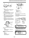
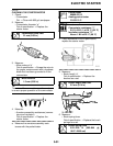
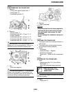
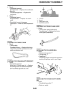
1. Remove:
• Timing chain guide (intake side) “1”
• Timing chain “2”
• Crankshaft sprocket “3”
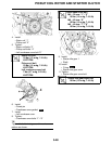
2. Remove:
• Neutral switch “1”
• Crankcase bolts M6 × 70 mm “2”–“4”
• Copper washers
• Crankcase bolts M6 × 60 mm “5”, “6”
• Crankcase bolts M6 × 55 mm “7”–“9”
• Crankcase bolts M6 × 45 mm “10”–“13”
TIP
Loosen each bolt 1/4 of a turn at a time, in
stages and in a crisscross pattern. After all of
the bolts are fully loosened, remove them.
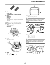
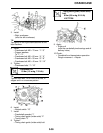
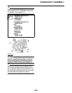
3. Turn:
• Shift drum segment
TIP
Turn the shift drum segment “1” to the position
shown in the illustration. In this position, the
shift drum segment’s teeth will not contact the
crankcase during crankcase separation.
4. Remove:
• Right crankcase
ECA13910
• First check that the shift drum segment’s
teeth and the drive axle circlip are prop-
erly positioned, then remove the right
crankcase.
• Do not damage the crankcase mating sur-
faces.
EAS25580
CHECKING THE CRANKCASE
1. Thoroughly wash the crankcase halves in a
mild solvent.
2. Thoroughly clean all the gasket surfaces
and crankcase mating surfaces.
3. Check:
•Crankcase
Cracks/damage → Replace.
• Oil delivery passages
Obstruction → Blow out with compressed
air.
EAS25690
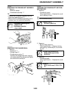
ASSEMBLING THE CRANKCASE
1. Apply:
• Yamaha bond No.1215 (Three Bond
No.1215®) “1”
(onto the crankcase mating surfaces)
TIP
Do not allow any sealant to come into contact
with the oil gallery.
2. Install:
• Dowel pins “2”
Yamaha bond No.1215
(Three Bond No.1215®)
90890-85505