


ENGINE
3-4
EAS20472
ENGINE
EAS20520
ADJUSTING THE VALVE CLEARANCE
The following procedure applies to all of the
valves.
TIP
• Valve clearance adjustment should be made
on a cold engine, at room temperature.
• When the valve clearance is to be measured
or adjusted, the piston must be at top dead
center (TDC) on the compression stroke.
1. Remove:
• Seat
• Front fender
• Fuel tank
Refer to “GENERAL CHASSIS” on page
4-1.
Refer to “FUEL TANK” on page 6-1.
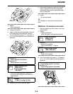
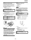
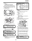
2. Remove:
• Spark plug cap
• Spark plug
• Cylinder head side cover 1 “1”
• Cylinder head side cover 2 “2”
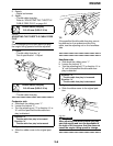
3. Remove:
• Timing mark accessing screw “1”
• Crankshaft end accessing screw “2”
4. Measure:
• Valve clearance
Out of specification → Adjust.
▼▼▼▼▼▼▼▼▼▼▼▼▼▼▼▼▼▼▼▼▼▼▼▼▼▼▼▼▼▼
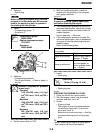
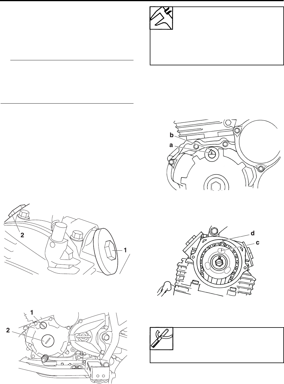
a. Turn the crankshaft counterclockwise.
b. When the piston is at TDC on the compres-
sion stroke, align the mark “a” on the
pickup coil rotor with the stationary pointer
“b” on the left crankcase cover.
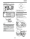
c. Align the mark “c” on the camshaft sprocket
with the stationary pointer “d” on the cylin-
der head.
d. Measure the valve clearance with a thick-
ness gauge “1”.
Out of specification → Adjust.
Valve clearance (cold)
Intake valve
0.05–0.10 mm (0.0020–0.0039
in)
Exhaust valve
0.10–0.15 mm (0.0039–0.0059
in)
Thickness gauge
90890-03180
Feeler gauge set
YU-26900-9