


6 RF LAYOUT CONSIDERATIONS
70 Copernicus GPS Receiver
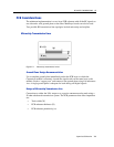
General Recommendations
The design of the RF transmission line that connects the GPS antenna to the
Copernicus GPS Receiver is critical to system performance. If the overall RF system
is not implemented correctly, the Copernicus GPS Receiver performance may be
degraded.
The radio frequency (RF) input on the Copernicus GPS module is a 50 ohm,
unbalanced input. There are ground castellations, pins 2 and 4, on both sides of the
RF input castellation, on pin 3. This RF input may be connected to the output of an
LNA which has a GPS antenna at its input or to a passive antenna via a low-loss 50
ohm, unbalanced transmission line system.
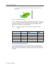
In the case where the GPS antenna must be located any significant distance from the
Copernicus GPS Receiver, the use of an LNA at the antenna location is necessary to
overcome the transmission losses from the antenna to the Copernicus GPS module. It
is recommended that in the case of a passive antenna, the transmission line losses
from the antenna to the module be less than 2 dB. Otherwise an LNA should be added
to the system.
The specifications for the external LNA required can be determined as follows. The
specification of noise figure for the Copernicus GPS module is 3 dB at room
temperature and 4 dB over the temperature range −40 C to ±85 C. The noise figure for
this external LNA should be as low as possible, with a recommended maximum of
1.5 dB. It is recommended that the gain of this LNA exceed the loss as measured from
the LNA output to the module input by 10 dB. For example, if the loss from the
external LNA output is 10 dB, the recommended minimum gain for the LNA is 20
dB. In order to keep losses at the LNA input to a minimum, it is recommended that
the antenna be connected directly to the LNA input, with as minimum loss as
possible.
Connections to either the LNA output or to a passive antenna must be made using a
50 ohm unbalanced transmission system. This transmission system may take any
form, such as microstrip, coaxial, stripline or any 50 ohm characteristic impedance
unbalanced, low-loss system.
It is important to keep any noise sources with frequencies at or near 1575 MHz away
from the RF input. In the case of a passive antenna, it is important that the antenna is
not placed in a noisy location (such as too close to digital circuitry) or performance
may be degraded. Shielded transmission line systems (stripline, coaxial) may be used
to route this signal if noise ingress is a concern.
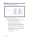
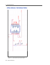
If an active antenna is used and it is desired to power this antenna from the RF
transmission line, a bias-tee will be required at the Copernicus GPS module end. A
simple series inductor (that is parallel resonant at 1575 MHz) and shunt capacitor
(series resonant at 1575 MHz) to which the bias voltage is supplied is sufficient. An
open/short detection and over current protection circuit may also be employed. Please
see Chapter 5, APPLICATION CIRCUITS.