


Copernicus GPS Receiver 37
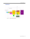
PRODUCT DESCRIPTION 2
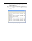
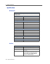
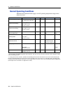
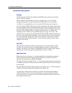
Absolute Minimum and Maximum Limits
Absolute maximum ratings indicate conditions beyond which permanent damage to
the device may occur. Electrical specifications shall not apply when operating the
device outside its rated operating conditions.
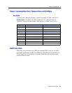
Note – See
Copernicus Standby Current, page 55 for information on the standby
current.
Parameter Min Max Unit
Power Supply
Power Supply Voltage (VCC) on
Pin 12
-0.3 3.6 V
STANDBY Voltage (VCC) on Pin
12 *
-0.3 3.6 V
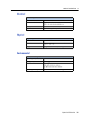
Antenna
Input Power at RF Input +10 dBm
Input Gain at RF Input 0 (passive
antenna)
36 dB
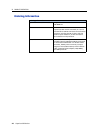
Input / Output Pin Threshold Levels
Input Pin Voltage (RXD-A, RXD-B, Open, Short, Reserved Pins, Xreset, Xstandby)
Status Min Max Unit
High 2.0 3.6 V
Low 0 0.8 V
Output Pin Voltage (TXD-A, TXD-B, LNA_XEN)
Status Min Max Unit
High (loh = 1 mA) 0.8 * VCC VCC V
Low (lol = 1 mA) 0 0.22 * VCC V