


3 INTERFACE CHARACTERISTICS
44 Copernicus GPS Receiver
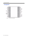
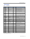
Detailed Pin Descriptions
RF Input
The RF input pin is the 50 ohm unbalanced GPS RF input, and can be used with
active or passive antennas.
Passive antennas: The RF input pin may be connected by a low-loss 50 ohm
unbalanced transmission system to the passive GPS antenna if loss is minimal
(< 2 dB). It is recommend that you use an external LNA with a passive antenna.
Active Antennas: The RF input pin can also be connected to the output of an external
low-noise amplifier, which is amplifying GPS signals from the antenna. The gain of
the LNA must be great enough to overcome transmission losses from the LNA output
to this pin. The specification for noise figure for the module is < 3 dB at room
temperature and < 4 dB over the specified temperature range, -40 to +85 C. The
external LNA must be located such that the loss from the GPS antenna connection to
the LNA input is minimized, preferably < 1 dB. The noise figure of the LNA should
be as low as possible, preferably< 2 dB. This specification is provided to enable a
cascaded noise figure design calculation. Active antennas must be powered with a
single bias-Tee circuit.
LNA_XEN
This logic level output can be used to control power to an external LNA or other
circuitry. The logic of this signal is such that when the module is running (not in
standby), this signal is low. During “STANDBY” mode, this signal is high. This pin
may be used to control the gate of a p-channel FET used as a switch.
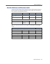
Open/Short Pins
When using an active antenna, it is recommended that you implement an antenna
detection circuit with short circuit protection. There are two pins provided for
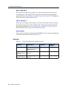
reporting the antenna status: OPEN and SHORT.
The logic level inputs outlined in Table 3.2 may be used with a detection circuit (with
or without protection) to monitor the status of the external LNA of an active antenna
by the module.
The truth table for the logic of these signals is provided in Table 3.2. These input pins
conform to the Input / Output Pin threshold levels specified in.
A typical active antenna draws between 10 to 20mA.The antenna Protect/Detect
circuit will trip as a short circuit at around 100mA. It is best to keep the antenna
current below 75mA. An open circuit will be determined if the antenna current falls
below approximately 2mA.