


C NMEA 0183
236 Copernicus GPS Receiver
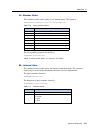
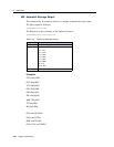
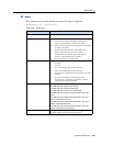
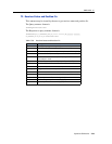
SG - Set Bit Mask for GPIOs in Standby Mode.
Users may designate individual pins for pull-down and pull-up while the unit is in
Standby Mode. This allows the user to select external pull-down or pull-up resistors
to suit their application.
Examples:
• In serial port configuration, one option would be to power down the serial port
during standby in which case the corresponding GPIOs would be pull-downs.
• To keep the serial port running during standby, the corresponding GPIOs would
be set to pull-ups.
Note – The pins that are not connected should remain in their default state, pull-
down.
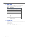
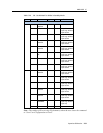
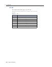
Use bit 5 of byte 1 to select the pull-down or pull-up resistor for the XTANDBY pin
as appropriate for the application. Unlike the other GPIOs, the selection of the pull-
down or pull-up resistor is applied during Run Mode.
Examples:
• When the XSTANDBY pin is tied to main power, as shown in the reference
design, select the pull-down resistor for the XTANDBY pin so when main
power is removed, XTANDBY is immediately pulled low to go into Standby
Mode.
• When the XTANDBY pin is controlled with GPIO on the user’s processor, the
pull-down or pull-up resistor may be selected depending on the GPIO state.
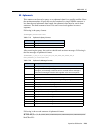
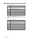
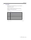
$PTNLxSG,hhhh*hh, <CR><LF>