


3 INTERFACE CHARACTERISTICS
46 Copernicus GPS Receiver
RXD_A and RXD_B
These logic level inputs are the primary (A) and secondary (B) serial port receive
lines (data input to the module). This output meets the input/output pin threshold
specifications (see Absolute Minimum and Maximum Limits, page 37.) The baud rate
for the two ports is under software control.
TXD_A and TXD_B
These logic level outputs are the primary (A) and secondary (B) serial port transmit
lines (data moving away from the module). This output meets the input/output pin
threshold specifications (see Absolute Minimum and Maximum Limits, page 37.)
The baud rate for the two ports is under firmware control.
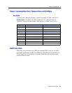
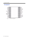
Reserved Pins
There are 8 reserved pins on the Copernicus GPS Receiver. For the recommended pin
connections for these reserved pins, see Table 3.1.
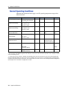
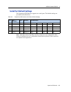
Protocols
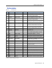
Table 3.3 Copernicus GPS Receiver Available protocols
Protocols Specification Direction Serial Port
Support
NMEA NMEA 0183 v3.0; Bi-
directional with extended
NMEA sentences
Input / Output Both Serial Ports
TSIP (Trimble
Standard Interface
Protocol)
Trimble propriety binary
protocol
Input / Output Both Serial Ports
TAIP (Trimble ASCII
Interface Protocol)
Trimble propriety ASCII
protocol
Input / Output Both Serial Ports