


Installation and Maintenance 51
,QVWDOODWLRQ&KHFN OLVW
The following is an abbreviated list of the detailed
installation information given in this manual and
should be used as an aid to ensure proper
installation. For complete instructions, refer to the
appropriate sections of the manual.
WARNING
Disconnect electrical power
source when servicing the unit.
Failure to do so may result in
injury or death from electrical
shock.
Secure drive sheaves before ser-
vicing the unit to ensure that rotor
cannot free-wheel. Failure to
secure drive sheaves can cause
severe personal injury.
1 Examine the unit and components for material
shortage or shipping damage.
2 Check unit location for unit dimensions, weights
and clearances.
3 Rig each section properly and hoist it to its final
position.
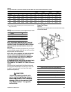
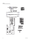
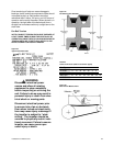
4 For split ship units with factory mounted controls,
connect color coded and numbered quick connect
plugs (reference
Figure 44
).
5 Check that unit is installed level.
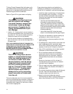
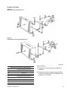
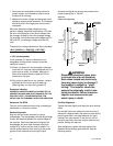
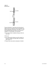
6 Remove fan isolator tie-down bolt, if unit is not
externally isolated. See
Figure 18
and
Figure 19
.
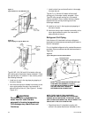
7 Inspect Inlet Guide Vanes and adjust if necessary.
8 Install damper operator motors and connecting
linkage. Check damper operation and linkage
alignment.
9 Install filters, if supplied.
10 Connect supply and return air ductwork.
11 Complete coil and condensate drain piping
connections.
12 Reference CLCH-IOP-1 for more details on the
installation of units with factory mounted controls.
13 Complete electrical connections to the unit and
PCM.
14 Leave the unit installation and maintenance
manual with the unit.
Prestart-Up Checks
Before operating the unit, complete the following
checks for safe and efficient operation.
WARNING
Disconnect electrical power
source when connecting or dis-
connecting electrical wires for test
procedures. Do not open service
access doors while the unit is
operating. Failure to exercise cau-
tion when completing test proce-
dures or while inspecting unit
operation may result in injury or
death from electrical shock, air
movement or rotating parts.
q Rotate all fan wheels manually. Fans should turn
freely in the proper direction.
q Check fan drive belt tension.
NOTE: IF T-SERIES CLIMATE CHANGER FAN IS
GOING TO OPERATE AT OTHER THAN DESIGN RPM
OR WITH A VARIABLE SPEED DRIVE NOT SUPPLIED
BY TRANE, THE UNIT VIBRATION LEVELS SHOULD
BE CHECKED AT THE NEW RPM AND THROUGHOUT
THE SPEED RANGE. RE-BALANCE OR CORRECT
VIBRATIONS AS NECESSARY.
q Check fan hub set screws, sheave set screws and
bearing set screws for proper torque (
Table 45
).
Fan sheaves should be tight and aligned. Bearing
set screws should be aligned. See section titled
“Periodic Maintenance” for alignment instructions.
q Inspect fan motor and bearings for proper
lubrication. Refer to
Table 49
for fan grease
recommendations. Contact the motor
Table 45
Fan Bearing Setscrew Torque Settings (lb-ft)
Screw Size Hex Size Torque
1/4
1/8 5.5-7.5
5/16
5/32 10.5-13.7
3/8
3/16 19-25
7/16
7/32 29-37.5
1/2
1/4 42-54.2