


Installation and Maintenance 49
Wiring
WARNING
Disconnect electrical power
source before servicing the unit or
connecting electrical wires.
Failure to do so may result in per-
sonal injury or death from electrical
shock or entanglement in moving
parts. If the unit includes a factory-
mounted starter, use of the lockout/
tagout on the disconnect is required
while servicing the unit.
If the unit does not include a factory-mounted starter,
wiring to the unit fan motor must be provided by the
installer and must comply with all national and local
electrical codes. The installer must also furnish a
fused disconnect switch in compliance with national
and local electrical codes. Fan motors require
overload protective devices rated or selected in
compliance with the National Electric Code or
Canadian Electric Code. Specific unit and motor
connection diagrams are attached to the unit.
CAUTION
Use copper conductors only for
terminal connections. Use of alu-
minum or other type of wiring may
result in galvanic corrosion or
overheating and resultant equip-
ment damage.
Fan motors require motor overload protective
devices that are rated or selected in compliance with
the National Electric Code or Canadian Electric
Code. Specific unit and motor connection diagrams
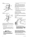
are provided on the unit. If wiring directly to the
motor, a flexible connection at the motor to permit fan
belt adjustment should be provided. Fractional
horsepower motors may be factory connected to a
terminal box on the unit. If this construction is
provided, the installer should complete field wiring to
this connection box.
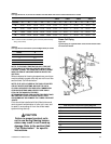
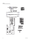
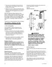
For a typical high voltage wiring schematic, see
Figure 44
following.
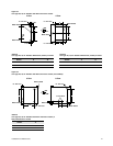
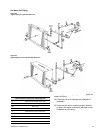
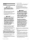
Connection of junction sections to unit end devices is
accomplished using the connections shown in
Figure
23
. See unit control drawings for specific connection
information.
For typical field wiring to units with DDC:
q Provide 120 VAC power for control. A dedicated
circuit is recommended. Units with a factory-
mounted starter or VFD do not require this circuit
as they are powered by the oversized control
transformer in the starter or VFD.
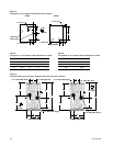
q If unit ships in multiple sections, fasten quick
connects (
Figure 23
) before sections bolt
together.
q Field mount and wire outside air sensor and
space sensor, if ordered.