40 CLCH-IM-16A
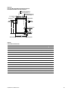
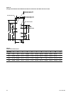
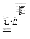
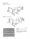
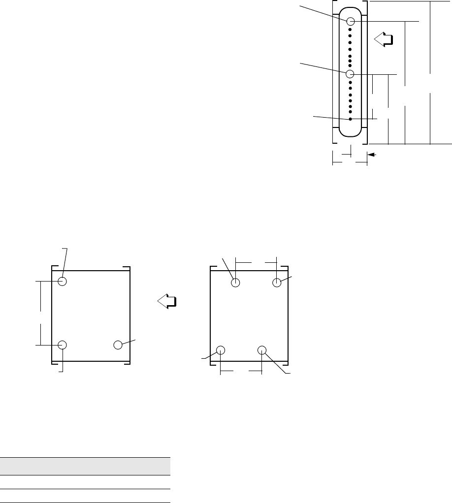
Figure 32
Coil Type WC-24” Headers with Drain and Vent Locations
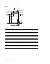
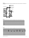
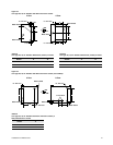
Figure 33
Coil Type P2, 18, 24” Headers with Drain and Vent Locations
AIR
FLOW
10-1/2”
12”
24-1/8”
25-1/2”
4”
2”
1-1/4” NPT (INT)
Return
1-1/4” NPT (INT)
Supply
Sq Hd Pipe Plug
1/2” NPT Drain
1/2” NPT Vent
1/2” NPT Vent
1/2” NPT Drain
Water Inlet
Water Outlet
Water Outlet
Water Inlet
A
6”
6”
AIR
FLOW
2, 4 Row 6 Row
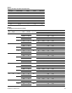
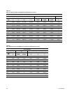
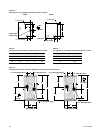
Table 37
Coil Type P2, 18, 24” Headers Dimensions (in)
Header
A
18 16.5
24 22.5


