


Installation and Maintenance 39
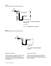
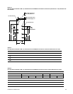
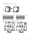
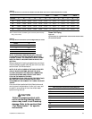
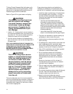
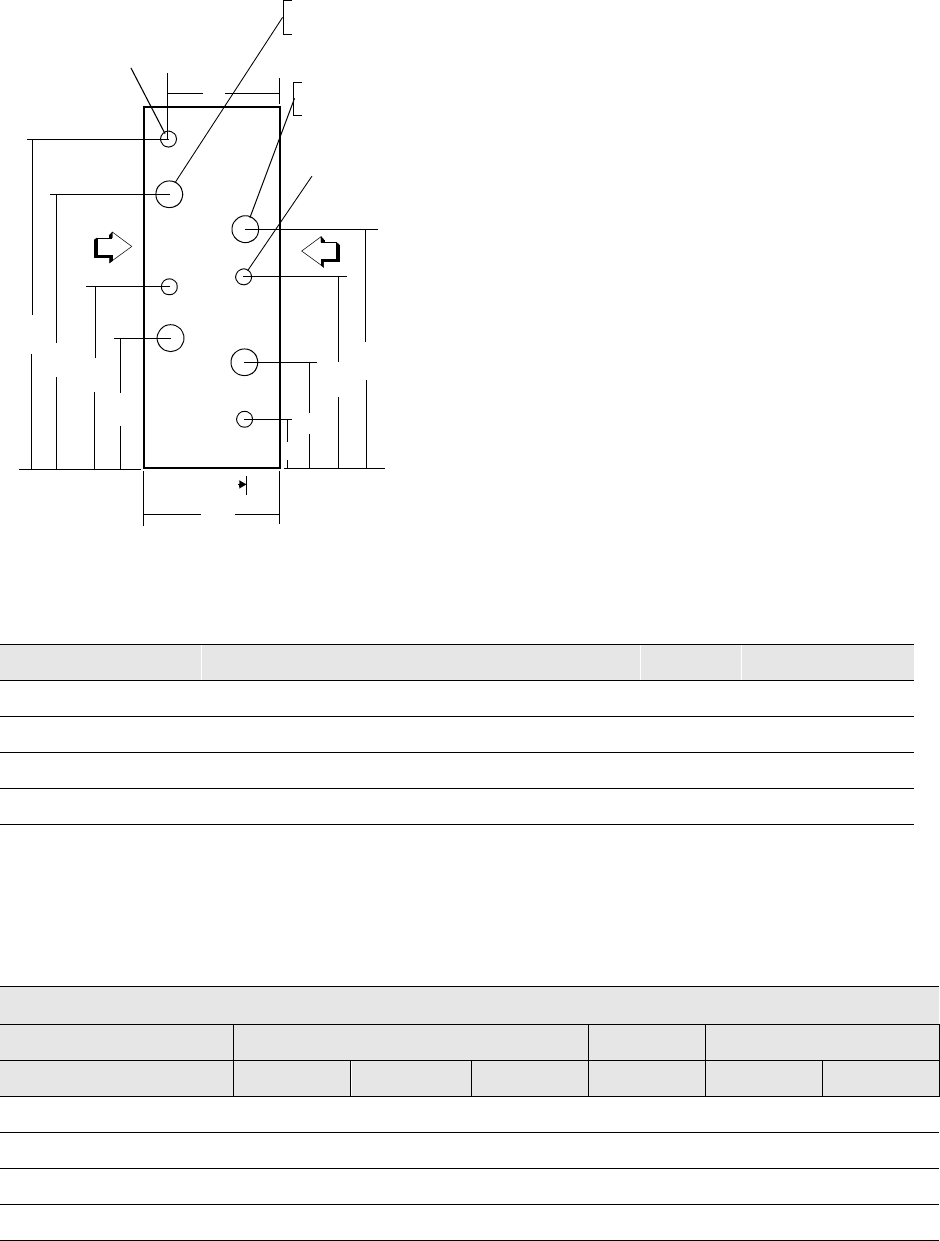
Figure 31
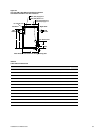
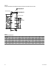
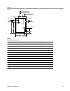
Coil Type UU 4 and 8-Row & UW 4, 6, and 8-Row RH and LH Medium Coil Section Connections (Unit Sizes 50 - 100) with Drain and
Vent Location
.
AIR
FLOW
AIR
FLOW
A
B
C
D
E
F
G
J
K
M
1’7”
R NPT (EXT) Supply R.H.
R NPT (EXT) Return L.H.
R NPT (EXT) Return R.H.
R NPT (EXT) Supply L.H.
3/8” NPT Ext Vent
3/8” NPT Ext Drain
Left Hand
Right Hand
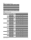
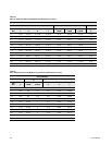
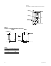
Table 35
Coil Type UU 4 and 8-Row & UW 4, 6, and 8-Row RH and LH Medium Coil Section Connections Dimensions in inches
Unit Size A B E F G J K M R
50
18-3/4 21-7/8 60 35-5/8 39 52-3/4 55-7/8 69-5/8 2
66
27-3/4 30-7/8 11-1/2 47-1/8 50-1/2 66-3/4 69-7/8 74-1/8 2
80
31-1/2 34-5/8 11-1/2 54-5/8 58 42 81-1/8 101-1/8 2-1/2
100
34-11/16 37-3/4 11-1/2 60-11/16 64-1/4 87-3/8 90-7/16 113-5/8 2-1/2
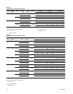
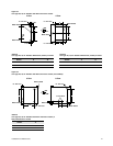
Table 36
Coil Type UU 4 and 8-Row & UW 4, 6, and 8-Row RH and LH Medium Coil Drain and Vent Location Dimensions in inches
UW COIL SECTION UU COIL SECTION
D D
Unit Size C 4 ROW 6 ROW 8 ROW C 4 ROW 8 ROW
50 5-1/8 8-3/8 10-1/2 12-11/16 5-5/8 7-13/16 12-1/8
66 5-1/8 8-3/8 10-1/2 12-11/16 5-5/8 7-13/16 12-1/8
80 5-1/ (130.2) 8-3/8 10-1/2 12-11/16 5-5/8 7-13/16 12-1/8
100 5-1/8 8-3/8 10-1/2 12-11/16 5-5/8 7-13/16 12-1/8