


44 CLCH-IM-16A
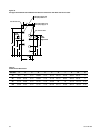
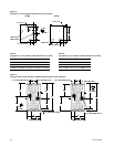
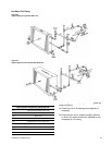
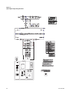
T-Series Climate Changers fitted with steam coils
have labeled holes for piping penetrations. Check
that the coil is installed correctly and that the unit
installation agrees with the submittals.
Refer to
Figure 38
for typical steam coil piping.
CAUTION
Condensate must flow freely from
the coil to prevent coil damage
from water hammer, unequal ther-
mal stresses, freeze-up damage
and corrosion. Complete the fol-
lowing recommendations to pre-
vent damage:
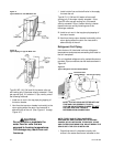
1 Install a 1/2” 15 swing-check vacuum breaker in
the unused condensate return connection at the
top of the coil. This vacuum breaker should be
installed as close to the coil as possible.
2 Vent the vacuum breaker to the atmosphere or
pipe it to the return main at the discharge side of
the steam trap.
NOTE: VACUUM BREAKER RELIEF IS MANDATORY
WHEN THE COIL IS CONTROLLED BY A MODULATING
STEAM SUPPLY OR TWO-POSITION (ON-OFF)
AUTOMATIC STEAM SUPPLY VALVE. VACUUM
BREAKER RELIEF IS ALSO RECOMMENDED WHEN
FACE AND BYPASS CONTROL IS USED.
CAUTION
The 1/2” 15 swing-check vacuum
breaker is recommended because
of the low cracking pressure of 3-
to 5-inches of water. Some other
vacuum breakers, such as spring
loaded ball-check vacuum break-
ers, have cracking pressures as
high as 17-inches of water. Substi-
tution of the 1/2” 15 swing-check
vacuum breaker could result in
damage to the coil by preventing
proper evacuation of condensate
from the coil.
The coil condensate return line must be piped full
size of the condensate trap connection, except for a
short nipple screwed directly into the coil headers
condensate return tapping. Do not bush or reduce
the coil return tapping size.
Proper steam trap selection and installation is
necessary for satisfactory coil performance and
service life. For installation, use the following steps:
1 Install the steam trap discharge 12 inches below
the condensate return connection. 12 inches
provides sufficient hydrostatic head pressure to
overcome trap losses and ensures complete
condensate removal.
*
Use float and thermostatic traps with
atmospheric pressure gravity condensate
return, with automatic controls or where the
possibility of low pressure supply steam exists.
Float and thermostatic traps are recommended
because of gravity drain and continuous
discharge operation.
*
Use bucket traps ONLY when the supply
steam is not modulated and 25 psig or higher.
2 Trap each coil separately to prevent holding up
condensate in one or more of the coils.
3 Install strainers as close as possible to the inlet
side of the trap.
4 If installing coils in series airflow, control each coil
bank independently with a automatic steam
control valve. Size the traps for each coil using the
capacity of the first coil in direction of airflow.
5 Use a V-Port modulating valve to obtain gradual
modulation of the coil steam supply.
6 Do not modulate systems with overhead or
pressurized returns unless the condensate is
drained by gravity into a receiver, vented to
atmosphere and returned to the condensate
pump.
7 Slowly turn the steam on full for at least 10
minutes before opening the fresh air intake on
units with fresh air dampers.
8 Pitch all supply and return steam piping down 1-
inch per 10 feet in the direction of the steam or
condensate flow.
9 Do not drain the steam mains or take-offs through
the coils. Drain the mains ahead of the coils
through a steam trap to the return line.
10 Assure continuous condensate removal.
Overhead returns require 1 psig of pressure at the
steam trap discharge for each 2-foot elevation.