


24 CLCH-IM-16A
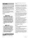
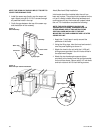
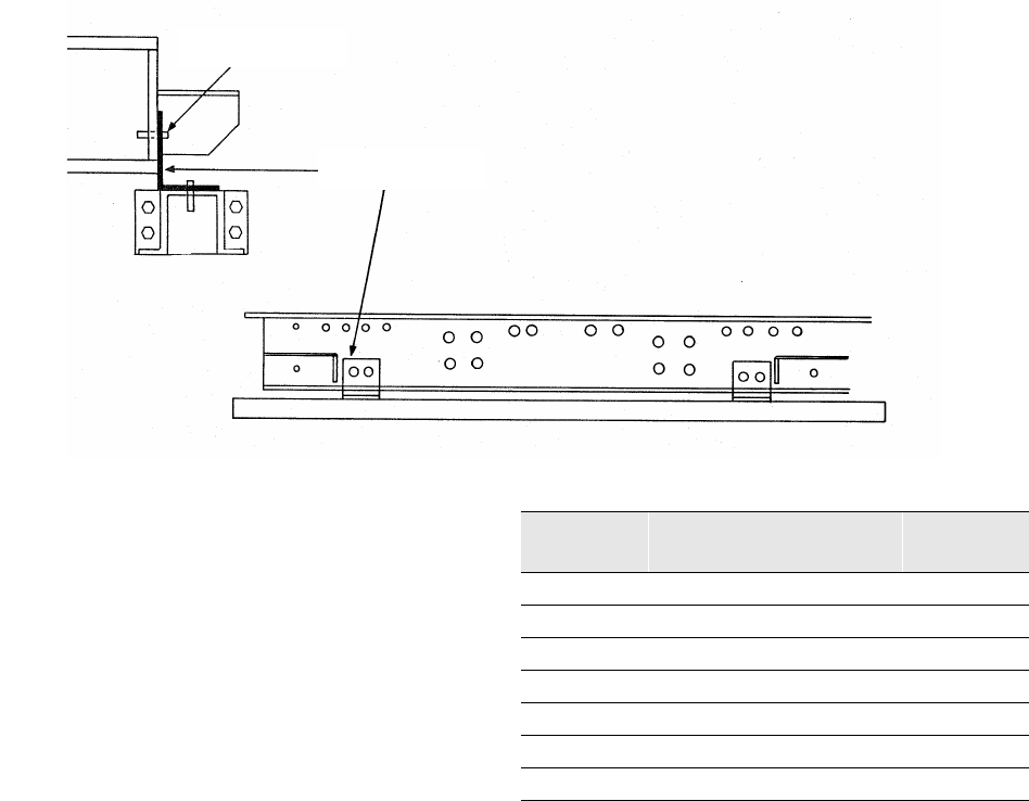
Figure 19
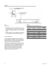
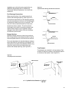
Shipping Angle and Isolator Tie-down Removal for Unit Sizes 66, 80 and 100 (Includes Plug Fans)
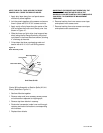
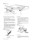
Remove the shipping tie-downs per the following
instructions:
1 Shipping tie-downs are located at each corner of
the isolation base. Access for removal of shipping
spacer is available through the fan module access
doors.
2 Remove the bolt. This will release the isolator and
make it possible to remove the pipe or spacer.
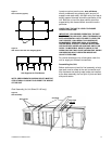
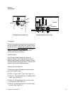
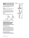
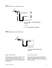
Isolator Adjustment
Once the shipping tie-downs are removed and the
internal isolation is released, it may be necessary to
adjust the isolators to achieve the proper operation
height of the fan and motor isolation base.
The isolators are bolted between the fan and motor
isolation base. There are five designs based on unit
size and fan type. Specific isolator clearances are
listed in
Table 23
. The measurement is taken
between the top of the floor panel (or support
channel on sizes 66-100) and the bottom of the
isolation base channel for all sizes.
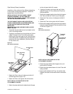
Angle, Isolator Tie-Down
(Four Required)
Screw, Lockwasher and Hex Nut
(Four per Angle)
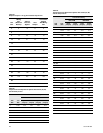
Table 23
Isolator Minimum Clearance Adjustments (in)
Unit Size Fan Type Isolator Type
Req’d
Clearance
3-8
FC Rubber 1.0
3-8
FC Spring 1.0
10-30
FC Rubber 0.5
10-30
FC and BI Spring 0.5
21-50
Plug Spring 0.5
35-50
FC & AF Spring 0.5
66-100
FC, AF & Plug Spring 1.0