


Installation and Maintenance 17
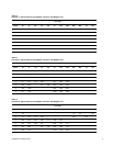
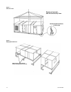
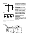
Figure 7
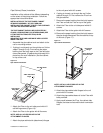
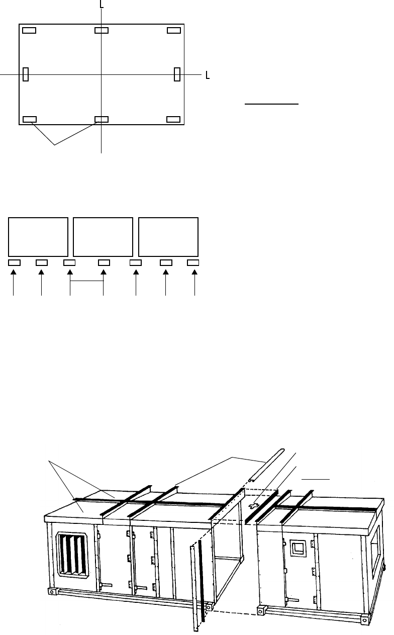
Pier Locations (Typical)
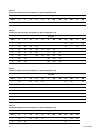
Figure 8
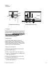
Side View of Unit with Two Shipping Splits
NOTE: PIERS BENEATH SHIPPING SPLITS MUST BE
STRUCTURALLY SOUND TO SUPPORT THE WEIGHT
OF THE UNIT
Locate one pier at each corner, as a minimum,
directly underneath any shipping split (ensure full
support under each side), and then every four feet at
equally spaced intervals around the perimeter of the
unit. Both the unit and the pipe cabinet should be
supported by their base channel around the entire
perimeter.
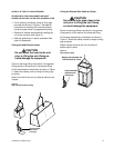
CHECK THAT THE UNIT IS LEVEL TO ENSURE
PROPER OPERATION.
IMPORTANT
: FOR PROPER OPERATION, THE UNIT
MUST BE INSTALLED LEVEL (ZERO TOLERANCE) IN
BOTH HORIZONTAL AXES. FAILURE TO LEVEL THE
UNIT PROPERLY CAN RESULT IN CONDENSATE
MANAGEMENT PROBLEMS SUCH AS STANDING
WATER INSIDE THE UNIT. STANDING WATER AND
WET SURFACES INSIDE AIR HANDLING UNITS CAN
RESULT IN MICROBIAL GROWTH (MOLD) IN THE
DRAIN PAN THAT MAY CAUSE UNPLEASANT ODORS
AND SERIOUS HEALTH-RELATED INDOOR AIR
QUALITY PROBLEMS.
For vertical discharge units, allow space under the
unit for supply air ductwork connections.
Assembling the Unit
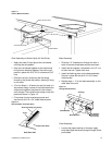
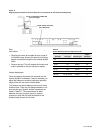
Before sections are joined for final assembly, a butyl
tape seal must be made at the roof connection and
then hardware and sealing metal strips are installed
at the base assembly, the roof joint or joints and both
side panel seams.
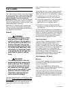
Roof Assembly (for Unit Sizes 50-100 only)
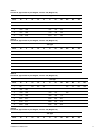
Figure 9
Roof Assembly
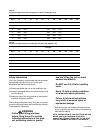
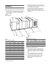
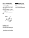
Piers
C
C
4’ Typ
Unit Supports for Pier Mounts
Butyl Tape
Joint Strip
Cross
Roof Panels
(2 Rows)