


Installation and Maintenance 47
coil nameplate or casing. The suction connection
must be at the bottom of the suction header.
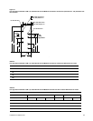
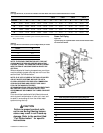
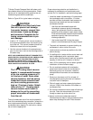
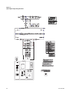
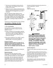
2 Follow accepted refrigeration piping practices and
safely precautions for typical refrigerant coil piping
and components. See
Figure 43
. Specific
recommendations are provided with the highside
components, including instructions for pressure-
testing, evacuation, and system charging.
General recommendations for component
selection and line sizing follow.
3 Leak-test the entire refrigeration system after all
piping is complete.
4 Charge the unit according to approximate weight
requirements, operating pressures and
superheat/subcooling measurements.
5 Adjust the thermal expansion valve setting if
necessary.
General Refrigerant Piping
Recommendations
IMPORTANT: REFER TO THE NOTE ON THE INSIDE
FRONT COVER OF THIS MANUAL REGARDING
HANDLING OF REFRIGERANTS
Liquid Line Components
Trane recommends the use of a properly sized liquid
line filter-drier installed upstream from the expansion
valve and as close to the evaporator coil as possible.
Base filter-drier selection on a maximum pressure
drop of 2 psi at the design condition.
1 Install moisture indicator/sight glass between the
expansion valve and filter-drier. The moisture
indicator/sight glass must be sized to match the
size of the liquid line at the thermal expansion
valve.
2 Size liquid line shutoff valve with an access port
using the selected liquid line OD, and install it
close to the condenser.
3 Minimize use of other valves, tube bends and
reducers since these items tend to increase
pressure drop and to reduce subcooling at the
expansion valve. Liquid line receivers, other than
those factory-installed, are not recommended.
4 The Thermal Expansion Valve (TEV) must be
selected for proper size and capacity. The size of
the TEV should cover the full range of loadings.
Check that the valve will successfully operate at
the lightest load condition. Also consider the use
of a hot gas bypass valve when sizing the TEV.
Select expansion valves with external equalizer
connections, and those designed to operate
against a back pressure of 20 pounds per square
inch higher than actual evaporator pressure.
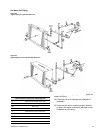
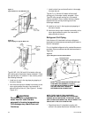
5 Install the TEV directly on the coil liquid
connection (distributor) provided. The liquid
distributor must be in a true vertical position.
CAUTION
Disassemble the thermal expan-
sion valve before completing the
brazing connections. If necessary,
wrap the valve in a cool, wet cloth
while brazing. Failure to protect
the valve from high temperatures
may result in damage to the inter-
nal components.