


Installation and Maintenance 25
6HW8S
Once the T-Series Climate Changer is assembled
and installed, attention must be directed to individual
components for proper operation.
Dampers
(Including filter mixing sections, mixing sections, face
and bypass dampers and Traq dampers)
Before installing the Mixing sections fitted with filter
racks, be sure adequate clearance is provided to
open the access doors and install the filters. Filter
installation is explained in the section titled “Filter
Installation.”
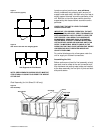
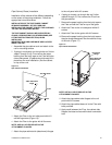
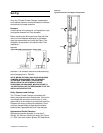
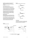
Figure 20
Typical Mixing Box Configuration (sizes 3-100)s
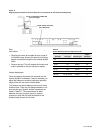
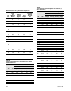
actuators. The actuators should be sized according
to the torques given in
Table 24
.
NOTE: MIXING SECTIONS, AND FACE AND BYPASS
DAMPERS ARE DESIGNED, FOR THE DAMPER
ACTUATORS TO BE DIRECT COUPLED AND
INSTALLED IN THE AIR STREAM. IF OTHER
PROVISIONS ARE REQUIRED, MODIFICATIONS TO
THE SECTION WILL BE THE RESPONSIBILITY OF THE
INSTALLING CONTRACTOR.
Rods, Operators and Settings
The T-Series Climate Changer is available with
factory mounted controls or end devices. If the unit is
not ordered with controls or end devices, it is the
responsibility of the installer to provide and install the
Dampers are factory installed and adjusted. There
are three damper blade configurations available:
parallel blade, opposed blade, and Traq dampers.
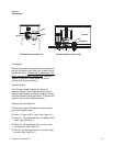
Opposed and Parallel Dampers
Opposed and parallel dampers in units size 3
through 100 have an internal jack-shaft. See
Figure
21
. A 90
°
jack shaft rotation gives a 95
°
blade travel.
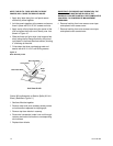
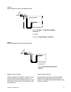
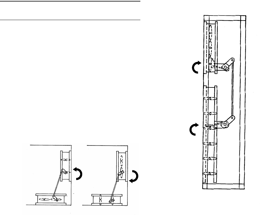
Figure 21
Typical Internal Face and Bypass Configuration
Open
Close