


Installation and Maintenance 15
,QVWDOODWLRQ
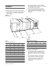
When preparing the unit site, consider the following:
1 Ensure that the site can support the total weight of
the unit.
Table 1
and
Table 2
list approximate
section weights.
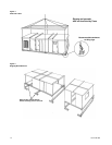
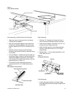
2 Allow sufficient space for the recommended
service access. Refer to
Figure 6
for FC, BI and
AF fan wheels and for plug fans.
3 Confirm that the foundation of the mounting
platform is large enough to include the unit
dimensions. Refer to unit submittals for specific
dimensions.
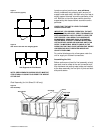
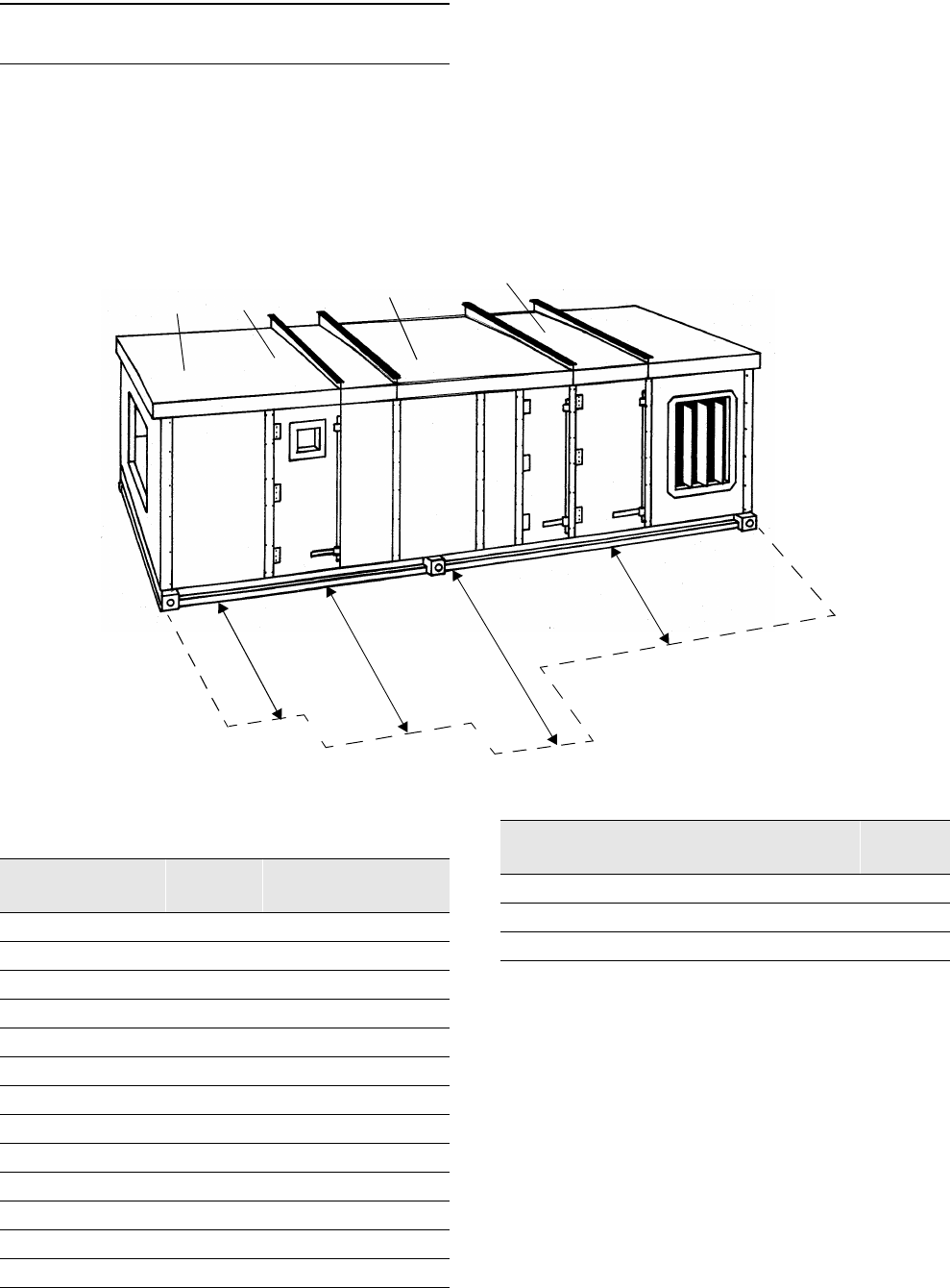
Figure 6
Service Clearances
The floor or foundation must be level for proper coil
drainage and condensate flow.
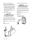
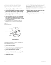
4 Allow the proper height for condensate drain
requirements. Insufficient height may inhibit
condensate drainage and result in flooding the
unit.
5 Provide adequate lighting for maintenance
personnel to perform maintenance duties.
6 Provide permanent power outlets in close
proximity of the unit for installation and
maintenance.
Coil
Filter
FanDrive
A
B
C
D
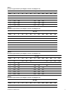
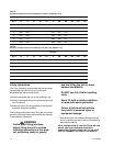
Table 22
Service Clearances (in inches)
Unit
Size
Filter A
Coil
Removal B
Fan C Starter D
3
48 48 48 60
6
48 60 48 60
8
48 64 48 60
10
48 75 51 60
12
48 79 54 60
14
48 83 58 60
17
48 89 61 60
21
48 91 60 60
25
48 93 66 60
30
48 106 66 60
35
48 110 65 60
40
48 123 70 60
50
48 134 77 60
66
52 150 93 60
80
56 150 91 60
100
58 165 101 60
Table 22
Service Clearances (in inches)
Unit
Size
Filter A
Coil
Removal B
Fan C Starter D