


2-2
VRC 6940 Product Reference Guide
!
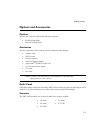
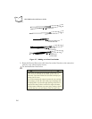
a drill with a 7/16” drill bit
!
7/16” hex wrench
!
primary or external antenna (optional)
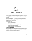
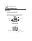
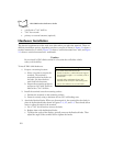
Hardware Installation
The physical requirements of the work area affect where you place the terminal. There are
different installation options, depending on where you plan to locate it. Figure 2-1 shows a
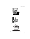
terminal mounted on a vehicle. Figure 2-2 shows a terminal mounted on a wall, and Figure
2-3 shows a terminal mounted on a workbench.
Caution
Do not install a VRC 6940 terminal in a location that will affect vehicle
safety or driveability.
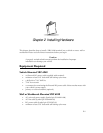
To install VRC 6940 hardware:
1. Prepare a mounting location:
a. Select a location to mount the
terminal. The terminal’s
attached bracket has holes cut
for bolts. Use these holes to
mark bolt hole locations.
b. Prepare the mounting surface to
accept two 3/8” bolts. Drill two
holes with a 7/16” drill bit.
2. Install the terminal onto the mounting surface:
a. Position the terminal on the mounting surface.
b. Fasten it securely using a minimum of two 3/8” self-locking nuts.
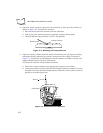
3. Attach the Bracket Knobs. When you first unpack it, the terminal has hex bolts in
place of the Bracket Knobs shown in Figures 2-1, 2-2, and 2-3. These knobs allow
users to adjust the angle of the terminal.
a. Use a 7/16” hex wrench to remove the bolts.
b. Replace them with the Bracket Knobs.
c. To adjust the angle of the display, partially unscrew the Bracket Knobs. Then
adjust the angle of the terminal and re-tighten the knobs.
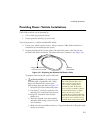
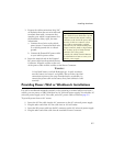
Installation Note: Mounting Locations
The bracket and terminal must be:
• firmly secured to a surface that can support
the terminal’s weight — on a vehicle, wall or
workbench
• secured with a minimum of two 3/8”
diameter bolts and nylon self-locking nuts
• easy to for end-users to see and reach