


61
APPLICATION NOTES
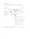
OutBack Power System GTFX/GVFX Grid-tie settings
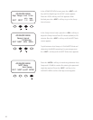
In a GFX/GVFX series inverter, MX60, HUB, and MATE installation set the MX60 to GT mode in the
ADVANCED MENU. The GT mode allows the GTFX/GVFX series inverter to manage the MX60 Float
setting ensuring the MX60 is always keeping the battery above the sell voltage of the GTFX/GVFX.
Grid-tie applications (non-OutBack inverter/chargers)
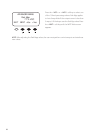
When selling electricity back to the grid, keep the inverter Sell/Float voltage below the MX60 Float
voltage. Appropriate values: 0.5 Volts di erence for 24V battery system or 1.0 volt di erence for 48V
battery systems.
Diversion using hydro or wind power
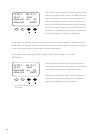
With wind or hydro generator applications, keep the MX60’s diversion voltage slightly above its Absorb
and Float voltages for e cient functioning.
Positive grounded systems
Telcom applications frequently require a positive grounded system. The MX60 switches the POSITIVE
PV and battery leads. Keep these separate. If code allows, ground ONLY the battery positive lead in
this case. Do not connect the MX60’s battery plus to the PV plus input while the MX60 is running. The
OutBack HUB cannot be used in a positive grounded system.
Battery temperature compensation with other slopes
The MX60 uses a -5mV per degree C per cell (2V) compensation slope required by UL. For other slopes,
you may be able to pick a di erent battery voltage and change the charger Absorb and Float voltage
settings to achieve a more or less aggressive slope. If going lower in voltage, reduce the Float voltage
rst, since the Absorb voltage will not be adjustable below the Float voltage setting. If going higher
in voltage, increase the Absorb setting rst before raising the Float voltage above the present setting.
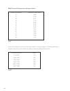
Here is a table of MX60 compensation based on system voltage for reference:
12V system -30mV/degree C
24V system -60mV/degree C
36V system -90mV/degree C
48V system -120mV/degree C
60V system -150mV/degree C