


10
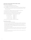
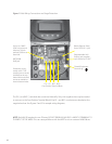
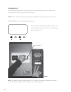
Use up to 2 AWG
(6.54 mm) wire and
torque to 30-inch
pounds/3.38 Nm at
terminals.
MATE/HUB
RJ45 jack
If attaching to ply-
wood, use a 1 5/8”
wood screw to secure
the MX60 at the top
slotted hole and other
screws as needed at
interior bottom holes.
PV+ PV- BAT- BAT+
Four-Position Terminal Block
Chassis/Equipment
Ground Lug
Programmable AUX
Output Jack (supplies
up to 200mA @ 12 VDC
Battery Remote Temp
Sensor (RTS) RJ11 jack
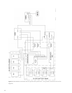
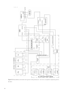
The PV (-) and BAT (-) terminals are connected internally. Only one negative wire may be needed
to connect to the Four-Position Terminal Block if the PV - and BAT- conductors are bonded at the
negative bus bar. See Figures 2 and 3 for sample wiring diagrams.
Figure 1 Field Wiring Connections and Surge Protection
NOTE: Each MX 60 requires its own PV array. DO NOT PARALLEL MX 60 PV+ AND PV- TERMINALS TO
THE INPUT OF THE MX60. This can cause problems with the MPPT and can cause an MX60 failure.