


9.18
Section 9
Disassembly
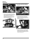
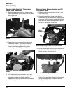
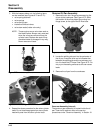
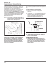
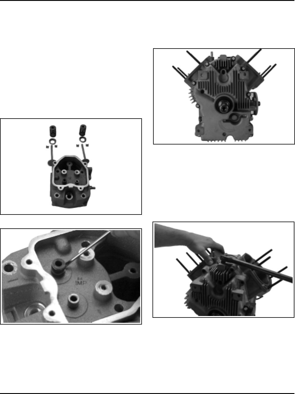
Figure 9-72. Removing Oil Pan Fasteners.
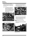
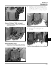
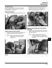
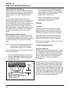
2. Locate the splitting tab cast into the perimeter of
the oil pan. Insert the drive end of a breaker bar
between the splitting tab and the crankcase, and
turn it to break the RTV seal. See Figure 9-73. Do
not pry on the sealing surfaces as this can cause
leaks.
3. Remove the oil pan from the crankcase.
Remove Oil Pan Assembly
1. Remove the ten hex. flange screws securing the
oil pan to the crankcase. See Figure 9-72. Note
the location of the silver plated (grounding) hex.
flange screw, to the right of the oil filter boss.
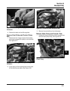
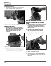
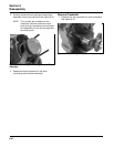
3. With the keepers taken out, the following items
can be removed (see Figures 9-70 and 9-71):
• valve spring retainers
• valve springs
• valve spring caps
• intake and exhaust valves
• valve stem seals (intake valve only)
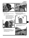
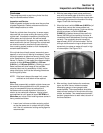
NOTE: These engines use a valve stem seal on
the intake valves. Always use a new seal
when the valves are removed from the
cylinder head. Replace the seals if they
are deteriorated or damaged in any way.
Never reuse an old seal.
Figure 9-70. Valve Components.
Figure 9-71. Removing Intake Valve Seal.
4. Repeat the above procedure for the other cylinder
head. Do not interchange parts from one cylinder
head with parts from the other cylinder head.
Figure 9-73. Splitting Oil Pan from Crankcase.
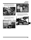
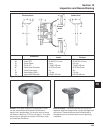
Governor Assembly (Internal)
The governor gear assembly is located inside the oil
pan. If service is required, refer to the service
procedures under ‘‘Governor Assembly’’ in Section 10.