


5.3
Section 5
Fuel System and Governor
5
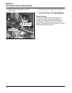
2. Remove the hex. flange screws (securing pump
to blower housing) and fuel pump.
3. Remove the vacuum line that connects the pump
to the crankcase.
4. Install a new pump using the hex. flange screws.
NOTE: Make sure the orientation of the new
pump is consistent with the removed
pump. Internal damage may occur if
installed incorrectly.
5. Connect vacuum line between pulse pump and
crankcase. Route line so there are no low spots
where oil could collect.
6. Tighten the hex. flange screws to 2.3 N·m
(20 in. lb.).
7. Connect the fuel lines to the inlet and outlet
fittings.
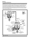
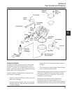
Carburetor
General
Engines in this series are equipped with fixed main jet
carburetors. Most applications also utilize a fuel shut-
off solenoid, which is installed in place of the fuel bowl
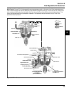
retaining screw. All carburetors feature the self-
relieving choke components shown in the exploded
view on page 5.9. These carburetors include three
main circuits which function as follows.
Float Circuit: Fuel level in the bowl is maintained by
the float and fuel inlet needle. The buoyant force of the
float stops fuel flow when the engine is at rest. When
fuel is being consumed, the float will drop and fuel
pressure will push the inlet needle away from the seat,
allowing more fuel to enter the bowl. When demand
ceases, the buoyant force of the float will again
overcome the fuel pressure and stop the flow.
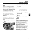
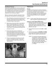
Fuel Pump
General
These engines are equipped with an external pulse
fuel pump. The pumping action is created by the
oscillation of positive and negative pressures within
the crankcase. This pressure is transmitted to the
pulse pump through a rubber hose connected between
the pump and crankcase. The pumping action causes
the diaphragm on the inside of the pump to pull fuel in
on its downward stroke and to push it into the
carburetor on its upward stroke. Two check valves
prevent fuel from going backward through the pump.
Performance
Minimum fuel delivery rate must be 7.5 L/hr.
(2 gal./hr.) with a pressure at .3 psi and a fuel lift of
24". A 1.3 L/hr. (.34 gal./hr.) fuel rate must be
maintained at 5 Hz.
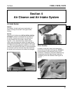
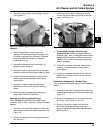
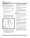
Replacing the Fuel Pump
Replacement pumps are available through your
source of supply. To replace the pulse pump follow
these steps. Note orientation of pump before
removing.
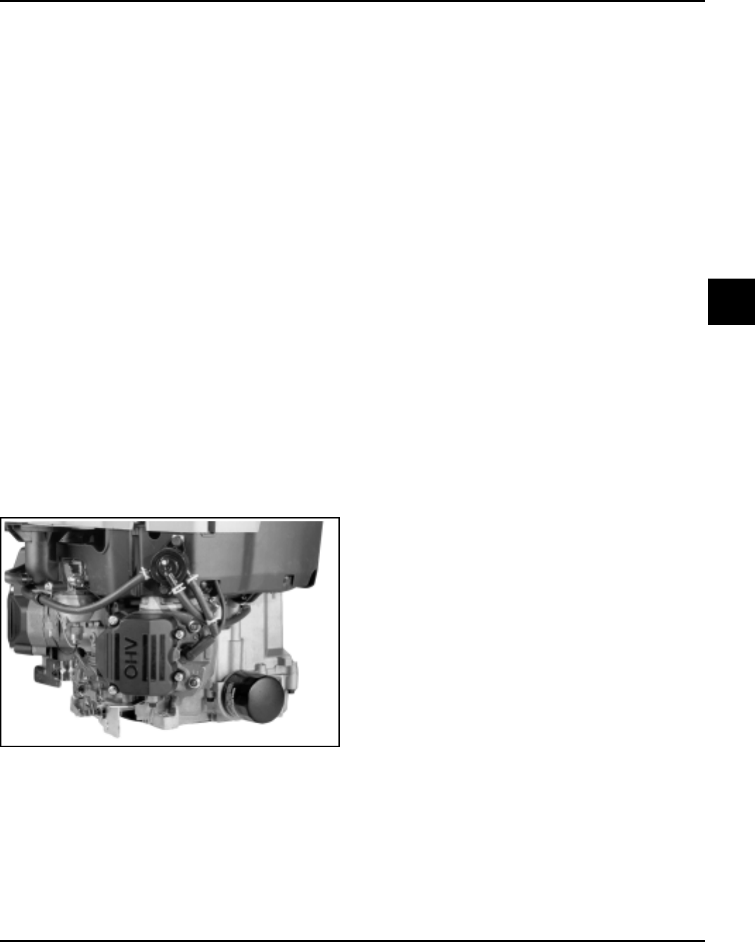
1. Disconnect the fuel lines from the inlet and outlet
fittings.
Figure 5-1. Fuel Pulse Pump Connections.